Digital link-based switching reactive compensation control device and method

A digital link, compensation control technology, applied in reactive power compensation, reactive power adjustment/elimination/compensation and other directions, can solve the problem of not paying attention to capacitance capacity, line susceptible to interference, reactive power compensation manager and current transformer Long distance and other problems, to avoid low reactive power compensation efficiency, accurate and reliable capacitor switching operation, and avoid frequent switching phenomenon.

Active Publication Date: 2021-01-29
宁波大家小家网络科技有限公司
View PDF12 Cites 0 Cited by
  • Summary
  • Abstract
  • Description
  • Claims
  • Application Information

AI Technical Summary

Problems solved by technology

[0005] 1. The reactive power compensation manager needs to read the current transformer installed in the incoming main cabinet to obtain reactive electrical data, but the distance between the reactive power compensation manager and the current transformer is generally far away, and the line is easily disturbed, resulting in Inaccurate measurement of electrical quantities;
[0006] 2. Most switching reactive power compensation systems only compensate the reactive power data on the low-voltage incoming line side (380V), but cannot compensate the reactive power incoming line on the high-voltage outgoing line side (10kV), resulting in reactive power compensation cabinets There is no way to accurately compensate the reactive power consumed by the transformer;
[0007] 3. The switching reactive power compensation system will not detect the state of the contactor, and cannot notify the user in time when the contactor fails, and the failure of the contactor will directly lead to low compensation efficiency, low power factor, and increase the burden on the transformer, and may cause security issues;
[0008] 4. The switching reactive power compensation system does not pay attention to the capacity of the capacitor, and cannot achieve accurate switching, and even frequent switching occurs

Method used


Image

  • Digital link-based switching reactive compensation control device and method
  • Digital link-based switching reactive compensation control device and method
  • Digital link-based switching reactive compensation control device and method

Examples


Embodiment Construction

[0067] Below in conjunction with accompanying drawing, technical scheme of the present invention will be further described:

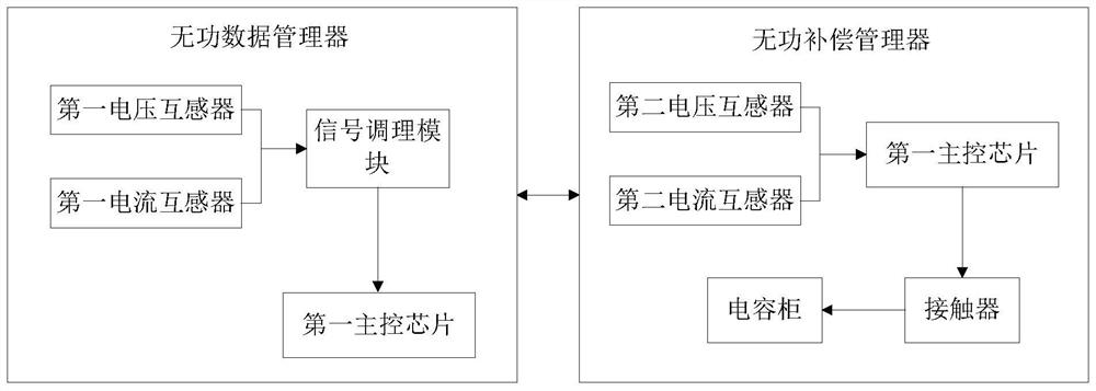
[0068] The present invention proposes a switching reactive power compensation control device based on a digital link, such as figure 1 As shown, it includes a reactive power data manager and a reactive power compensation manager. Among them, the reactive power data manager is used to collect the electrical data of the 380V low-voltage incoming line cabinet and the 10KV high-voltage outgoing line cabinet, and perform data processing on the electrical data to obtain reactive power data. And transmit the reactive power data to the reactive power compensation manager through the digital link; the reactive power compensation manager is used to perform reactive power compensation according to the reactive power data and capacitor switching logic, and to perform faults according to the electrical quantity of the capacitor cabinet and the state of the contactor ...


PUM


Abstract

The invention discloses a digital link-based switching reactive compensation control device and method, and aims to solve a technical problem of inaccurate reactive power compensation in the prior art. The device comprises a reactive data manager and a reactive compensation manager. The reactive data manager collects electrical data of a 380V low-voltage wire inlet cabinet and a 10KV high-voltagewire outlet cabinet, performs data processing on the electrical data to obtain reactive data, and transmits the reactive data to the reactive compensation manager through a digital link; and the reactive compensation manager performs reactive power compensation according to the reactive data and capacitor switching logic, and performs fault analysis and judgment according to an electrical quantityof a capacitor cabinet and a state of a contactor. According to the invention, the capacitor can be quickly and accurately switched, and reactive power compensation is carried out.

Description

technical field [0001] The invention relates to a switching reactive power compensation control device based on a digital link and a method thereof, belonging to the technical field of reactive power compensation in electric power systems. Background technique [0002] The electrical equipment in the power system will generate reactive power when it is in use, and it is usually inductive, which will reduce the capacity utilization efficiency of the power supply and cause power loss. The power factor is an important technical data of the power system, which can measure the efficiency of electrical equipment: a low power factor indicates that the reactive power of the circuit for alternating magnetic field conversion is large, which increases the loss of line power supply. In an AC circuit, the power factor can be calculated by the cosine of the phase difference (Φ) between the voltage and the current, represented by the symbol cosΦ. In numerical terms, the power factor is the...

Claims


Application Information

Patent Timeline
Patent Type & Authority Applications(China)
IPC IPC(8): H02J3/18
CPCH02J3/18Y02E40/30
Inventor 谢剑南傅佳琪余成
Owner 宁波大家小家网络科技有限公司
Why Eureka
Try Eureka