
Optical fiber stripping device related to new generation of information technology

An information technology, a new generation of technology, applied in the field of optical fiber stripping device, can solve the problems of heavy labor, difficult adjustment, fiber damage, etc., and achieve the effect of deep cutting depth

Inactive Publication Date: 2021-01-29
施亮(温州)软件开发有限公司
View PDF0 Cites 1 Cited by
  • Summary
  • Abstract
  • Description
  • Claims
  • Application Information

AI Technical Summary

Problems solved by technology

[0003] The optical fiber needs to be wired during construction, and the outer layer of the optical fiber needs to be stripped when wiring. Most of the existing stripping tools are press-type stripping equipment, that is, manually pressing the stripping equipment to peel the optical fiber, but this method requires a large amount of labor. After working for a long time, it will make the workers' hands sore and reduce the work efficiency, and it is not easy to control the amount of peeling when using this equipment, and the position of the optical fiber cannot be fixed accurately, resulting in damage and waste of the optical fiber; while the general automatic peeling equipment, peeling The depth is fixed, it is not easy to adjust, and the outer layer of the optical fiber with various thicknesses cannot be stripped
[0004] Aiming at the deficiencies of the prior art, the present invention provides an optical fiber stripping device related to a new generation of information technology, which has the advantages of being able to strip the outer layers of optical fibers of various thicknesses, and the operation is more labor-saving and simple, and solves the problems of the existing stripping methods. Problems with unsatisfactory results

Method used


Image

  • Optical fiber stripping device related to new generation of information technology
  • Optical fiber stripping device related to new generation of information technology
  • Optical fiber stripping device related to new generation of information technology

Examples


Embodiment Construction

[0027] The following will clearly and completely describe the technical solutions in the embodiments of the present invention with reference to the accompanying drawings in the embodiments of the present invention. Obviously, the described embodiments are only some, not all, embodiments of the present invention. Based on the embodiments of the present invention, all other embodiments obtained by persons of ordinary skill in the art without making creative efforts belong to the protection scope of the present invention.

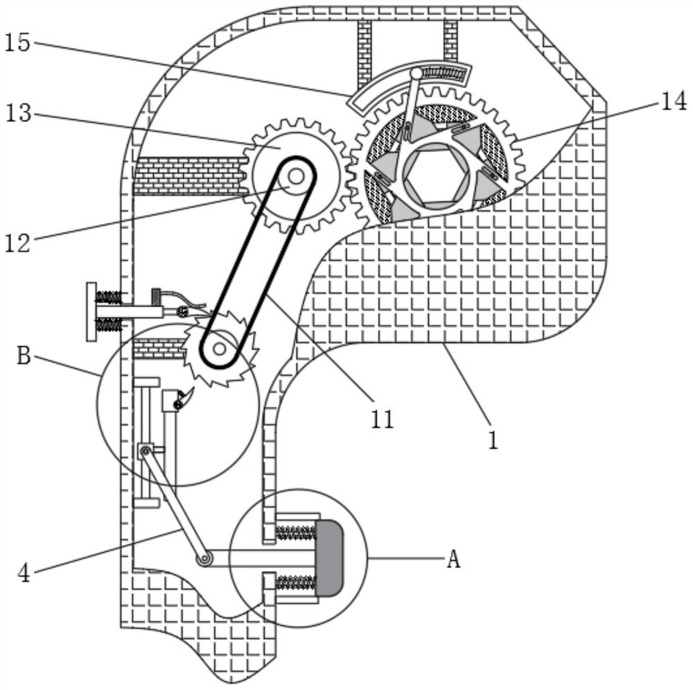
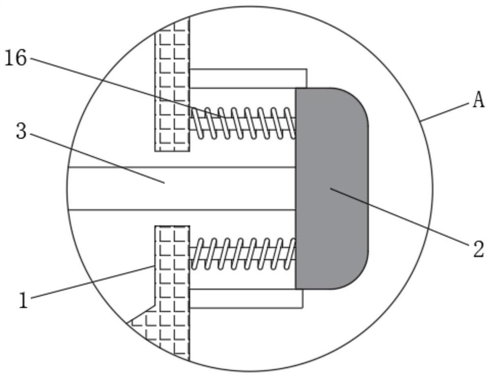
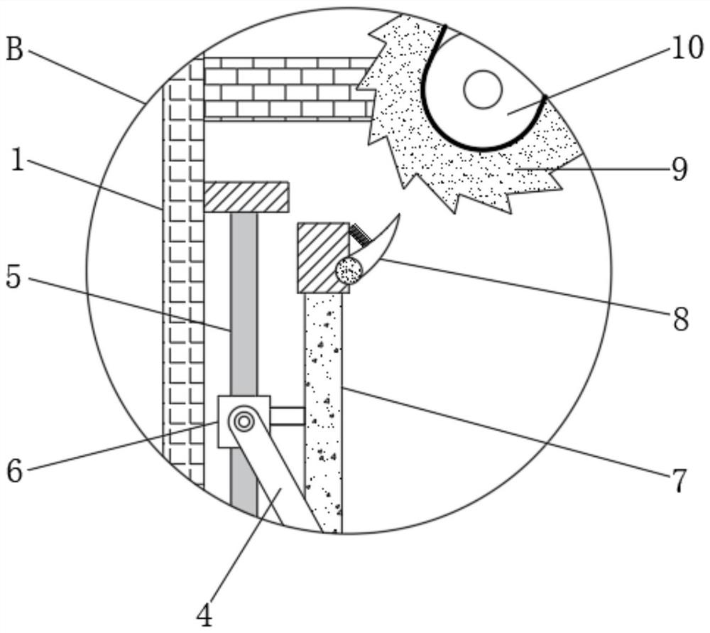
[0028] see Figure 1-6 , an optical fiber stripping device involving a new generation of information technology, including a housing 1, a button 2 is provided at the handle of the housing 1, and a return spring 16 is provided on the side of the button 2 close to the housing 1; the button 2 is close to the housing One side of 1 is fixedly connected with push rod 3, and the side of push rod 3 away from button 2 is movably connected with guide rod 4, and the side...


PUM


Abstract

The invention relates to the technical field of optical fiber equipment, and discloses a new generation information technology-related optical fiber stripping device which comprises a shell, a buttonis arranged at a grip of the shell, a push rod is fixedly connected to one side, close to the shell, of the button, and a guide rod is movably connected to one side, far away from the button, of the push rod. A sliding rod is arranged on the side, away from the push rod, of the guide rod, a sliding block is movably connected to the end, away from the push rod, of the guide rod, and a vertical rodis fixedly connected to the right end of the sliding block. According to the optical fiber stripping device related to the new generation of information technology, when an optical fiber is thick or aprotective sleeve is thick or the optical fiber needs to be cut off, the button needs to be pressed for multiple times, a ratchet wheel is driven by a pawl to intermittently rotate, namely, the clockwise rotating angle is increased, and the anticlockwise rotating angle of a gear ring is increased accordingly; therefore, the cutting depth of an iris cutting mechanism is deeper, the thicker outer-layer protective sleeve is peeled off or the optical fiber is completely cut off, and the effect of peeling off and cutting the optical fibers with various outer-layer thicknesses is achieved.

Description

technical field [0001] The invention relates to the technical field of optical fiber equipment, in particular to an optical fiber stripping device related to a new generation of information technology. Background technique [0002] Optical fiber, or optical fiber, is a fiber made of plastic or glass and is used as a tool for light transmission. In daily life, optical fibers are widely used for long-distance information transmission, such as optical fiber cables used in network information technology. [0003] The optical fiber needs to be wired during construction, and the outer layer of the optical fiber needs to be stripped when wiring. Most of the existing stripping tools are press-type stripping equipment, that is, manually pressing the stripping equipment to peel the optical fiber, but this method requires a large amount of labor. After working for a long time, it will make the workers' hands sore and reduce the work efficiency, and it is not easy to control the amount...

Claims


Application Information

Patent Timeline
IPC IPC(8): G02B6/245G02B6/44
CPCG02B6/245G02B6/566
Inventor 沈冰雁
Owner 施亮(温州)软件开发有限公司
Learn More