
A processing method for deep and narrow annular grooves on the stepped end face of a stepped shaft

A processing method and stepped shaft technology, applied in the processing field of deep and narrow ring grooves, can solve problems such as difficult quality assurance, too deep processing, and high processing difficulty, and achieve high processing efficiency, deep cutting depth, and fast processing speed. Effect

Active Publication Date: 2016-04-20
TONGYU HEAVY IND
View PDF4 Cites 0 Cited by
  • Summary
  • Abstract
  • Description
  • Claims
  • Application Information

AI Technical Summary

Problems solved by technology

[0002] At present, the hydropower industry has attracted attention at home and abroad. Hydropower has occupied an extremely important position in the history of energy development, supporting the sustainable development of the economy and society. The most important part of the turbine structure is the turbine shaft. At present, the turbine shaft at home and abroad is concerned. , most of them are stepped shafts, and there are deep and narrow ring grooves on the stepped end surface of the shaft body. For the equipment manufacturing industry, this kind of ring groove is difficult to process because of the narrow and deep groove. Use a horizontal lathe to process the deep and narrow ring groove. The technical difficulty is high, the operation requirements are high, and special equipment and technical means are required
The traditional processing method is difficult to process, takes a long time, consumes a lot of manpower and financial resources, and cannot be processed too deep. It can be processed to a depth of 300mm at most. After the groove is processed, there are many processing steps left in the groove, and it is difficult to ensure the roughness of the groove. Degree requirements, the quality of the tank is difficult to guarantee

Method used


Image

  • A processing method for deep and narrow annular grooves on the stepped end face of a stepped shaft
  • A processing method for deep and narrow annular grooves on the stepped end face of a stepped shaft
  • A processing method for deep and narrow annular grooves on the stepped end face of a stepped shaft

Examples


Embodiment Construction

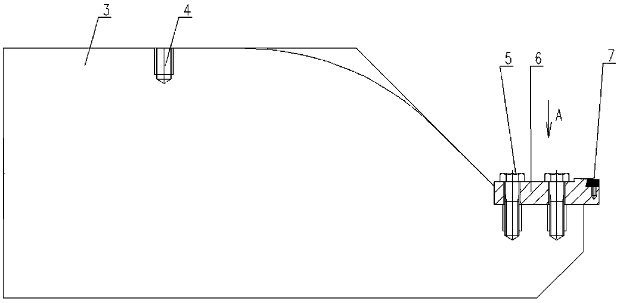
[0029] Such as Figure 6-12 A method for processing a deep and narrow annular groove on the stepped end face of a stepped shaft includes the following steps:

[0030] (1) Clamp and fix the workpiece 9 on the lathe chuck 8, and select the tangential cutter 12, such as figure 1 As shown, the tangent knife 12 includes a knife handle 2 and a knife head 1, and the knife head 1 is fixed on the front end of the knife handle 2, and the upper side of the knife handle 2 is flush with the upper side of the knife head 1, and the lower side of the knife handle 2 is formed by a knife The lower side of the head 1 is a stepped surface that gradually descends from the base. Such as Image 6 As shown, a circular groove 10 in which the inner wall is a circular hole surface and the outer wall is a stepped surface is cut out on the step end surface 11 of the workpiece 9 with a tangential cutter 12 .

[0031] (2) Select the reverse cutter 13 and replace the positive cutter 12, such as figure 2...


PUM


Abstract

The invention discloses a method for machining a deep narrow annular groove in the step end face of a stepped shaft. The method includes the following steps of firstly, cutting an annular groove with a step on one side wall in the step end face of a workpiece through a forward cutter; secondly, cutting the step produced in the last step flat through a backward cutter, and then further deepening the feed and cutting an annular groove with a step on the other side face through the backward cutter; thirdly, selecting the forward cutter for use to replace the backward cutter, cutting the step produced in the last step flat through the forward cutter, and then deepening the feed and cutting an annular groove with the step on the side face opposite to the side face mentioned in the last step through the forward cutter; fourthly, sequentially repeating the second step and the third step till the depth of the annular groove reaches the design depth-design depth machining allowance, wherein the basic width of the annular grooves in the first step, the second step, the third step and the fourth step reaches the design width-design width machining allowance; fifthly, conducting finish turning; sixthly, conducting grinding. By means of the method, it is ensured that enough strength is provided for the cutters, the cutters do not interfere with the workpiece, and therefore the cutting depth is large.

Description

technical field [0001] The invention relates to a processing method for a deep narrow ring groove on the stepped end surface of a stepped shaft. Background technique [0002] At present, the hydropower industry has attracted attention at home and abroad. Hydropower has occupied an extremely important position in the history of energy development, supporting the sustainable development of the economy and society. The most important part of the turbine structure is the turbine shaft. At present, the turbine shaft at home and abroad is concerned. , most of them are stepped shafts, and there are deep and narrow ring grooves on the stepped end face of the shaft body. For the equipment manufacturing industry, this kind of ring groove is difficult to process because of the narrow and deep groove. Use a horizontal lathe to process the deep and narrow ring groove. The technology is difficult, the operation is demanding, and special equipment and technical means are required. The tra...

Claims


Application Information

Patent Timeline
Patent Type & Authority Patents(China)
IPC IPC(8): B23P15/00
CPCB23P15/00
Inventor 司兴奎刘玉海王玉斌刘宝钢李凤曾
Owner TONGYU HEAVY IND
Learn More