Water outlet switching valve and combined shower

A technology for switching valves and water outlets, applied to valve details, multi-way valves, valve devices, etc., can solve the problems of complex valve core structure, high processing cost, cumbersome process steps, etc., and achieve simple structure, low production cost and excellent process The effect of requiring simplification

Pending Publication Date: 2021-01-29
XIAMEN SOLEX HIGH TECH IND CO LTD
View PDF0 Cites 0 Cited by
  • Summary
  • Abstract
  • Description
  • Claims
  • Application Information

AI Technical Summary

Problems solved by technology

This structure needs to involve multiple non-interfering waterways in the valve core, so the structure of the valve core is relatively complicated, the process steps during production are also relatively cumbersome, and the processing cost is high

Method used


Image

  • Water outlet switching valve and combined shower
  • Water outlet switching valve and combined shower
  • Water outlet switching valve and combined shower

Examples


Embodiment 1

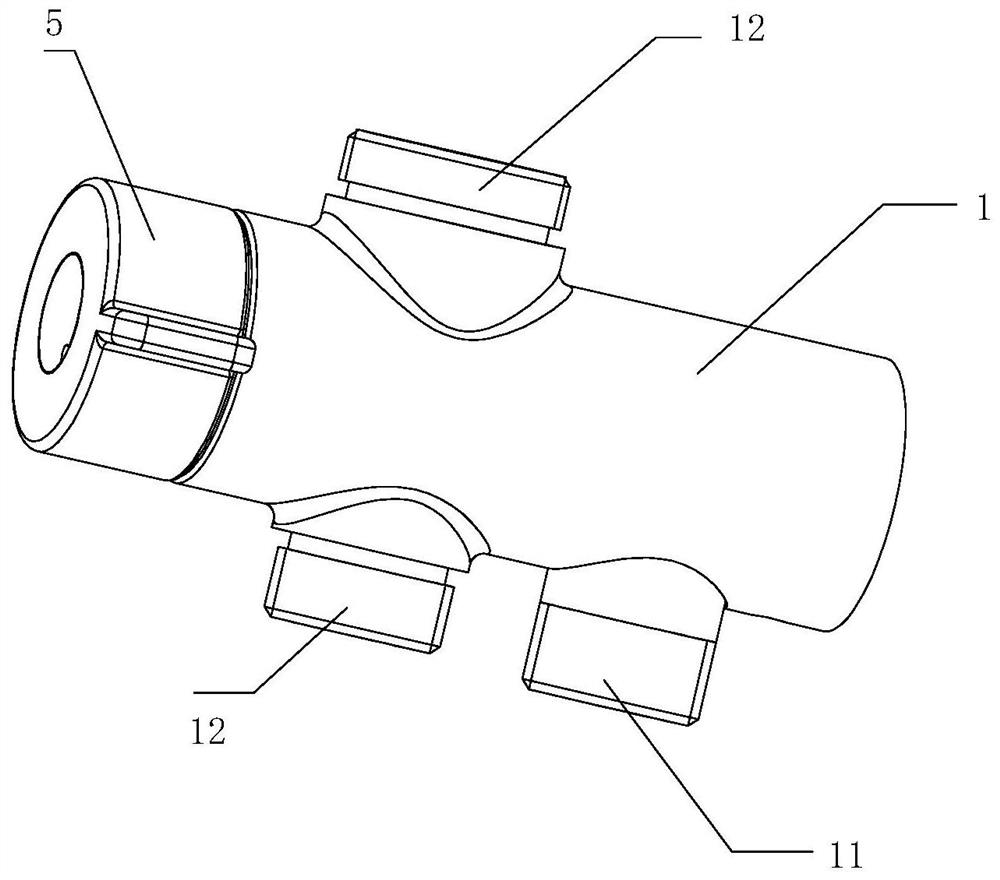
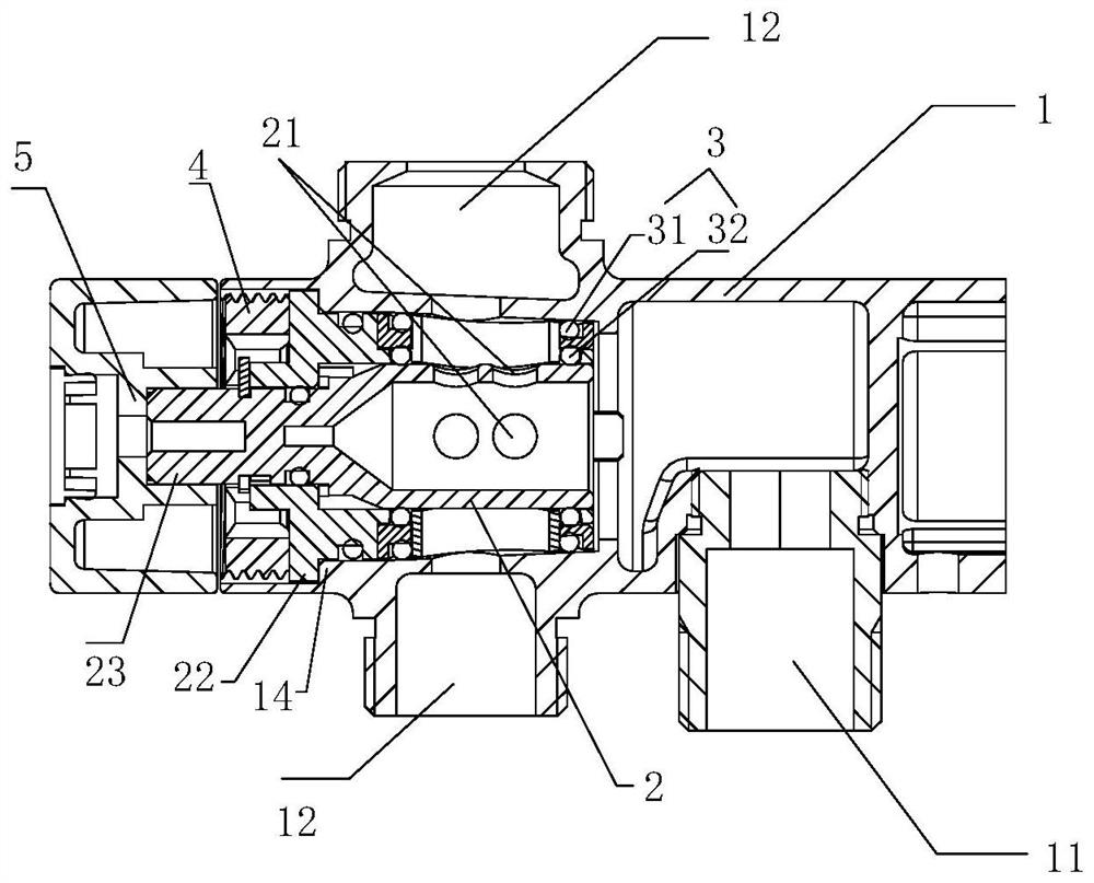
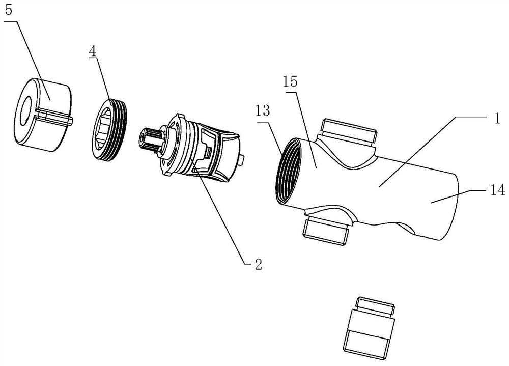
[0033] refer to Figure 1-Figure 5 , a water outlet switching valve, comprising: a casing 1 and a valve core 2;

[0034] The housing 1 has a water inlet 11 and two water outlets 12, the housing 1 includes a first end 15 and a second end 14, the second end 14 is connected to the wall, and the first end 15 is arranged on The other end of the shell 1 away from the wall is provided with an installation opening 13 at the first end 15, and the installation opening 13 is used to install the valve core 2; the number of water outlets 12 can be freely adjusted according to the number of water outlet terminals, if The water outlet switching valve is used in a combination shower. In order to supply water to the head shower and the hand shower, the number of water outlets 12 can be set to two.

[0035] The valve core 2 is placed in the housing 1 from the installation opening 13, and the outer wall of the valve core 2 and the inner wall of the housing 1 are sealed and connected at the oute...

Embodiment 2

[0044] refer to Figure 6-Figure 10 , this embodiment provides a water outlet switching valve, including: a valve core 6 and a valve core seat 7;

[0045] The valve core seat 7 has a water inlet hole 71 and at least two water outlet holes 72, and an installation opening 73 for installing the valve core 6; the number of water outlet holes 72 can be freely adjusted according to the number of water outlet terminals, if The water outlet switching valve is used in a combination shower. In order to supply water to the head shower and the hand shower, the number of water outlet holes 72 can be set to two.

[0046] The valve core 6 is placed in the valve core seat 7 from the installation opening 73, and the outer wall of the valve core 6 and the inner wall of the valve core seat 7 are sealed and connected at the outer periphery of the water outlet hole 72 through a seal 8, The water outlet hole 72 can only communicate with the valve core 6 located within the projected area of ​​the s...


PUM


Abstract

The invention provides a water outlet switching valve. The water outlet switching valve comprises a shell and a valve core; the shell is provided with a water inlet, at least two water outlets and a mounting opening for mounting the valve core; the valve core is arranged in the shell from the mounting opening, and the outer wall of the valve core and the inner wall of the shell are in sealed connection at the peripheries of the water outlets through sealing pieces, so that the water outlets can only be in communication with the portions, positioned in the projection area of the sealing pieces,of the valve core; the valve core is provided with a hollow cavity, the bottom end surface of the hollow cavity communicates with the water inlet, and the side surface of the valve core is provided with an opening communicating with the hollow cavity; and the valve core rotates in the shell in the axial direction of the valve core under the action of external force, and when the opening rotates into the projection area of one sealing piece, the water outlet corresponding to the sealing piece communicates with the water inlet through the opening and the hollow cavity for water outlet. According to the water outlet switching valve, the valve core is easy to install, a main body structure is simple, the machining process can be simplified, and the production cost can be reduced.

Description

technical field [0001] The invention relates to a water outlet device, in particular to a water outlet switching valve. Background technique [0002] For the control spool commonly used by multiple water outlet terminals, in addition to the function of switching water, it also needs to have the function of switching water channels, that is, switching between different water outlet terminals for water outlet. In the traditional water channel switching valve core, multiple water outlet channels are often designed. When the valve stem is operated, the valve stem drives the seal to seal one of the channel and open the other channel, thus completing the water channel switching. This structure needs to involve multiple non-interfering waterways in the valve core, so the structure of the valve core is relatively complicated, the process steps during production are also relatively cumbersome, and the processing cost is high. Contents of the invention [0003] The main technical p...

Claims


Application Information

Patent Timeline
Patent Type & Authority Applications(China)
IPC IPC(8): F16K11/085F16K5/04F16K27/06F16K27/08F16K31/60
CPCF16K11/085F16K5/0471F16K5/0407F16K27/065F16K27/08F16K31/605
Inventor 林方棋胡力宏但堂俊
Owner XIAMEN SOLEX HIGH TECH IND CO LTD
Why Eureka
Try Eureka