
Energy dual-redundancy system and control method thereof

A control method and dual-redundancy technology, applied in the field of servo control systems, can solve problems such as the inability to meet the high reliability requirements of manned moon landings, the inability to provide energy for the electro-hydraulic servo system, and failure to achieve fault isolation. Switching and miscutting phenomenon, meeting high reliability requirements, light weight effect

Active Publication Date: 2021-01-29
SHANGHAI AEROSPACE CONTROL TECH INST
View PDF8 Cites 1 Cited by
  • Summary
  • Abstract
  • Description
  • Claims
  • Application Information

AI Technical Summary

Problems solved by technology

The energy part of the traditional launch vehicle servo system basically adopts a single-redundancy design scheme, which makes it a single point of the system. Although the reliability can meet the needs of conventional satellite launches and cargo, it cannot meet the high reliability requirements of manned moon landing.
[0003] In addition, there are some researches on the redundant design of the energy section of the servo system. Some of them use high-pressure hoses to interconnect the inlet sections of the servo valves of the two sets of electro-hydraulic servo systems to form energy redundancy. If one energy source fails, the other channel cannot work normally. For others, although an energy selection valve is installed at the inlet section of the servo valve and a single pressure point is set, the auxiliary oil circuit will be switched if the pressure point is lower than this pressure point, and the auxiliary oil circuit will not be switched if the pressure point is higher than this pressure point. , but when the energy part fails, the inlet pressure may fluctuate at this pressure point, so that the energy selection valve will switch back and forth continuously, so that it cannot normally provide energy for the electro-hydraulic servo system

Method used


Image

  • Energy dual-redundancy system and control method thereof

Examples


Embodiment Construction

[0027] The present invention will be described in detail below in conjunction with specific embodiments. The following examples will help those skilled in the art to further understand the present invention, but do not limit the present invention in any form. It should be noted that those skilled in the art can make several changes and improvements without departing from the concept of the present invention. These all belong to the protection scope of the present invention.

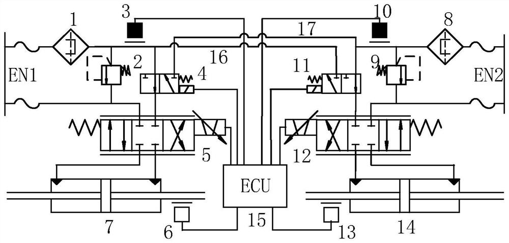
[0028] Such as figure 1 As shown, an energy dual redundancy system provided by the present invention includes: a controller 15, a main oil circuit and an auxiliary oil circuit.

[0029] The main oil circuit includes: the first essential oil filter 1, the first relief valve 2, the first energy selection valve 4, the first servo valve 5 and the first hydraulic cylinder 7, and the two ends of the first relief valve 2 are respectively connected to the first The high pressure circuit and low pressure circui...


PUM


Abstract

The invention provides an energy dual-redundancy system and a control method thereof. The energy dual-redundancy system comprises a controller, a main oil way and an auxiliary oil way. Each of the main oil way and the auxiliary oil way comprises a fine oil filter, an overflow valve, a servo valve, a hydraulic cylinder and a displacement sensor, and further comprises a pressure sensor, an energy selection valve, a high-pressure hose, a controller and a double-threshold logic control strategy. Automatic switching and fault isolation between the main oil way and the auxiliary oil way of an energypart are implemented, the structure is simple, the weight is light, and switching responding is fast. Because the double-threshold logic control strategy is applied, false switching between the mainoil way and the auxiliary oil way is avoided, the reliability of a servo system can be improved by one order of magnitude relative to a product in service, and the requirement for high reliability ofmanned aerospace lunar landing in China is met. The energy dual-redundancy system and the control method thereof belong to the field of electro-hydraulic servo systems.

Description

technical field [0001] The invention relates to the field of servo control systems, in particular to an energy dual redundancy system and a control method thereof. Background technique [0002] The electro-hydraulic servo system is widely used in the thrust vector control system of active launch vehicles because of its simple structure, mature technology, and fast dynamic response. The number of matching engine servo systems in each sub-stage of the launch vehicle is often an even number. The energy part of the electro-hydraulic servo system refers to The engine energy is exported to the energy regulation section of the servo valve inlet section. The energy part of the traditional launch vehicle servo system basically adopts a single-redundancy design scheme, which makes it a single point of the system. Although the reliability can meet the needs of conventional satellite launches and cargo, it cannot meet the high reliability requirements of manned moon landing. [0003] I...

Claims


Application Information

Patent Timeline
IPC IPC(8): F15B21/02F15B13/08F15B13/044F15B21/041
CPCF15B21/02F15B13/086F15B21/041F15B2013/0448F15B2211/6336F15B2211/6306F15B2211/6656F15B2211/8757
Inventor 张仲良田欢张鑫彬房成李文顶刘洪宇
Owner SHANGHAI AEROSPACE CONTROL TECH INST
Learn More