Building construction discharging platform device

A technology of unloading platform and building construction, which is applied in the processing of building materials, construction, building construction, etc., and can solve problems such as inconvenient operation and reducing the contact stress between the unloading platform and the limit baffle

Inactive Publication Date: 2021-01-29
姚正平
View PDF1 Cites 3 Cited by
  • Summary
  • Abstract
  • Description
  • Claims
  • Application Information

AI Technical Summary

Problems solved by technology

[0003] Chinese patent (notification number: CN107816210A) discloses a construction unloading platform device, including a support guide rail, the outside of the support guide rail is provided with more than six groups of fixed plates equidistant and symmetrically distributed, and one end of the support guide rail is connected to a The two sets of columns symmetrically distributed are equipped with hooks on the side of the fixed boss close to the connecting plate, and the upper side of the support guide rail is provided with a discharge platform, which can be moved on the support guide rail, which is convenient for construction and unloading. The rope can balance the force on both ends of the supporting guide rail and maintain the balance of force. The guardrail can protect the life safety of the constructor. The pressure boss can ensure the force balance of the supporting guide rail during unloading construction. The contact stress between the unloading table and the limit baffle, the combination of the lock column and the insert plate make the side door and the guardrail relatively fixed, the electric telescopic rod can conveniently control the relative stillness of the unloading table and the support guide rail, and the anti-slip friction plate can make the material table and the support The guide rail is relatively static, but the device can only unload on one plane, which makes the operation more inconvenient, so the device needs to be improved

Method used


Image

  • Building construction discharging platform device
  • Building construction discharging platform device
  • Building construction discharging platform device

Examples


Embodiment 1

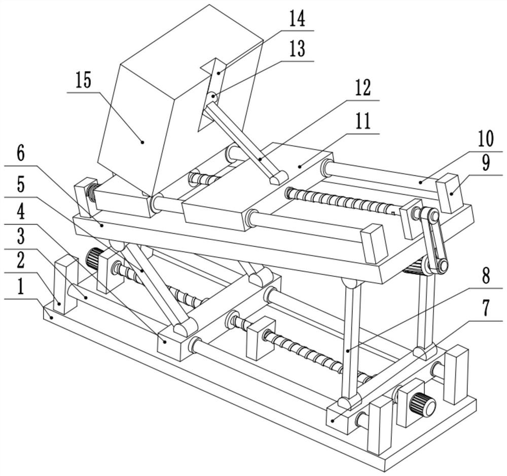
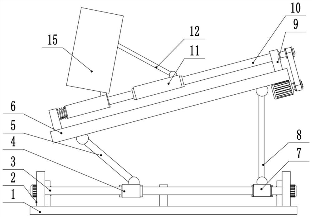
[0028] see Figure 1-6 , a construction unloading platform device, comprising a turntable 6, the upper surface of the turntable 6 is provided with a second fixed plate 9 on the front and rear sides, the middle part of the second fixed plate 9 is provided with a second guide rod 10, and the second guide The left side of bar 10 slides and connects the fourth sliding seat 17, and the right side of the fourth sliding seat 17 rotates and connects the left end of hopper 15, and the lower surface right end of described turntable 6 is provided with first drive motor 25, and the first drive motor 25 The output shaft of the output shaft is fixedly connected to the first pulley 24, the first pulley 24 is connected to the second pulley 22 through the belt 23, the second pulley 22 is fixedly connected to the right end of the first screw mandrel 19, and the middle part of the first screw mandrel 19 is threaded. The middle part of the 3rd slide seat 11, the upper surface right side of the 3r...

Embodiment 2

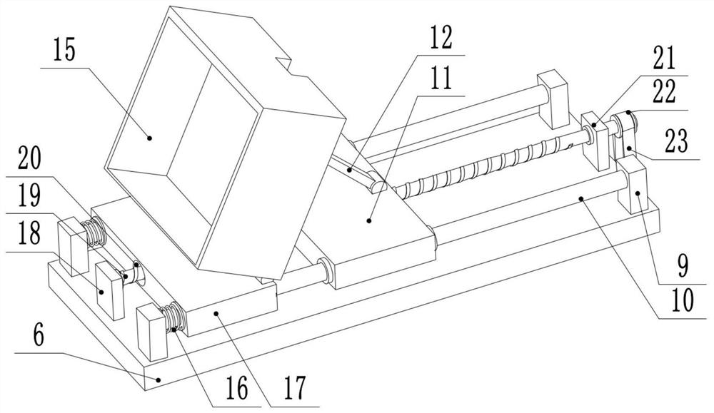
[0032] see image 3 , the other content of this embodiment is the same as that of the first embodiment, except that: the left side of the second guide rod 10 is sheathed with a spring 16 . In order to avoid the collision between the fourth sliding seat 17 and the second fixed plate 9 when moving, a spring 16 is provided on the left side of the second guide rod 10, so that the second fixed plate 9 and the fourth sliding seat 17 are buffered by the spring 16 As a result, rigid contact is avoided.

[0033]In the implementation process of the present invention, start the second drive motor 26, the second drive motor 26 drives the second screw mandrel 28 to rotate, the second screw mandrel 28 drives the first sliding seat 4 to slide to the right, and starts the third drive motor 32 at the same time , the third driving motor 32 drives the third screw mandrel 30 to rotate, the third screw mandrel 30 drives the second sliding seat 7 to slide to the left, when the first sliding seat 4...


PUM


Abstract

The invention relates to the technical field of building construction, and discloses a building construction discharging platform device. The building construction discharging platform device comprises a rotating table, second fixing plates are arranged on the front side and the rear side of the upper surface of the rotating table, second guide rods are arranged in the middles of the second fixingplates, a fourth sliding base is slidably connected to the left sides of the second guide rods, the right side of the fourth sliding base is rotationally connected with the left side of a hopper, theleft side of the lower surface of the rotating table is rotationally connected with the upper ends of first supporting rods, the lower ends of the first supporting rods are rotationally connected with the front end and the rear end of the upper surface of a first sliding base, the front side and the rear side of the first sliding base are slidably connected with the left sides of first guide rods, the right sides of the first guide rods are slidably connected with the front side and the rear side of a second sliding base, and the front end and the rear end of the upper surface of the second sliding base are rotationally connected with the lower ends of second supporting rods. According to the building construction discharging platform device, by arranging the first sliding base and the second sliding base which can move left and right, the height and the angle of the hopper can be freely adjusted.

Description

technical field [0001] The invention relates to the technical field of building construction, in particular to a building construction unloading platform device. Background technique [0002] The unloading platform is a variety of temporary operating platforms and operating frames that are often set up on the construction site, and is generally used for material turnover. The unloading platform is divided into mobile unloading platform, floor unloading platform and cantilever unloading platform. At present, in the construction process of high-rise buildings, it is often necessary to build various temporary unloading platforms for carrying and transferring materials within a certain period of time. The unloading platforms are divided into mobile, floor-standing, cantilevered, etc. Since the unloading platform is an operating platform temporarily set up outside the main body of the building, once a safety accident occurs, it is very easy to cause heavy casualties and property...

Claims


Application Information

Patent Timeline
IPC IPC(8): E04G21/16
CPCE04G21/166
Inventor 姚正平
Owner 姚正平
Why Eureka
Try Eureka