A six-bar mechanism for a footed robot
A six-bar mechanism and robot technology, applied in the field of robots, can solve the problems of inability to adapt to complex terrain environment, movement speed, energy efficiency disadvantage, etc., and achieve the effect of solving the problem of hard landing
- Summary
- Abstract
- Description
- Claims
- Application Information
AI Technical Summary
Problems solved by technology
Method used
Image

Examples
Embodiment 1
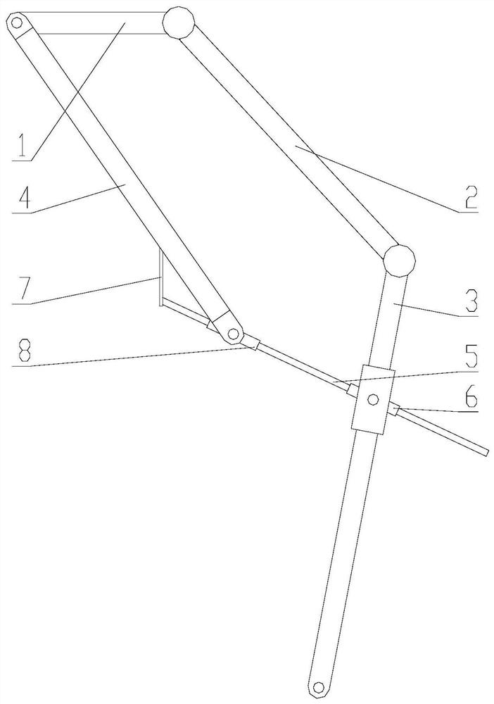
[0018] Such as figure 1 , the present invention provides a schematic structural diagram of a six-bar mechanism for a legged robot, the six-bar mechanism includes a hip bar 1, a thigh bar 2, a calf bar 3, an upper passive bar 4, a lower passive bar 5, a first rotating Slider mechanism 6, elastic member 7 and second rotary slider mechanism 8; one end of said hip rod 1 is connected with one end of thigh rod 2 through a rotary joint, and the other end of said thigh rod 2 is connected with one end of calf rod 3 The connection is rotatable through a revolving joint, which refers to a revolving joint containing a driving device, which can make two connected parts rotate relative to each other, and realize the movement of the six-bar mechanism through the coordinated driving of the two revolving joints. One end of the first rotating slider mechanism 6 is movably connected with the other end of the calf bar 3 through a rotating shaft; the other end of the hip bar 1 is movably connected...
Embodiment 2
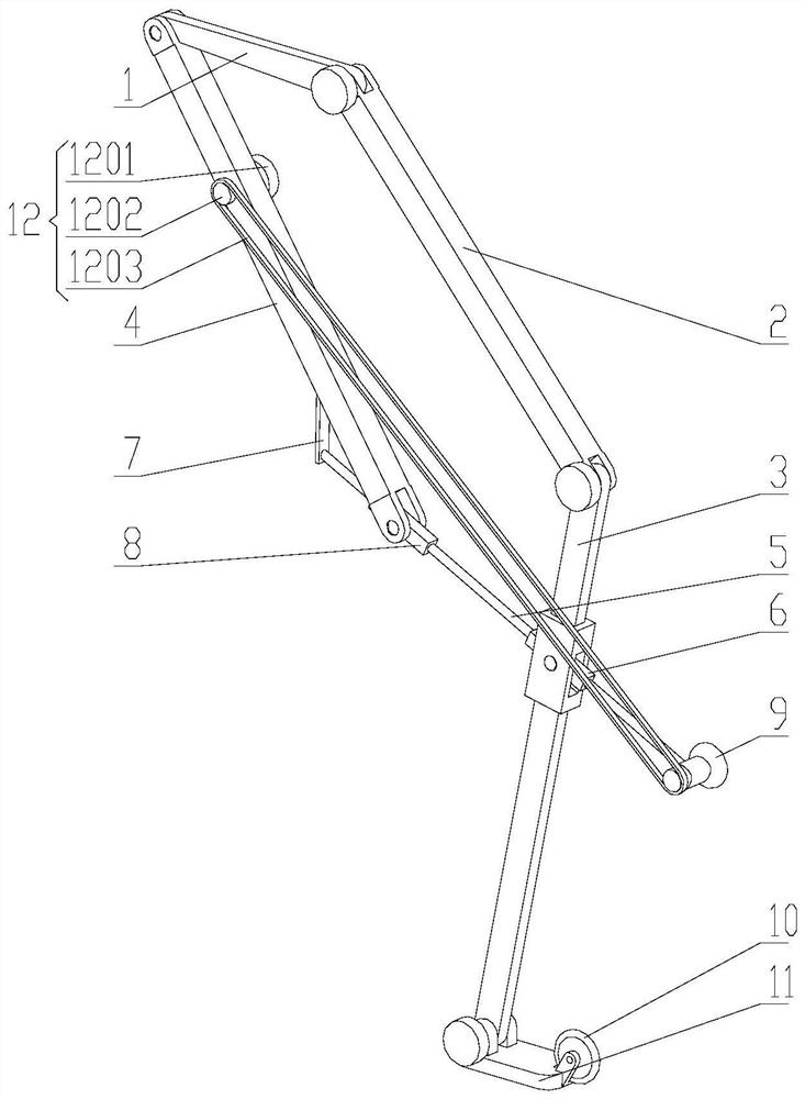
[0020] Such as figure 2 , the present invention also provides a structural schematic diagram of a six-bar mechanism for a legged robot, the six-bar mechanism also includes: a driving wheel 9, a driven wheel 10, a mechanical foot 11 and a driving device 12, the driving wheel 9 and One end of the lower passive rod 5 close to the first rotary slider mechanism 6 is movably connected through a rotating shaft, and the lower end of the mechanical foot 11 and the lower leg rod 3 is movably connected through a rotating shaft, and the rotating joint connecting the lower end of the lower leg rod 3 and the mechanical foot 11 The calf rod 3 and the mechanical foot 11 can be relatively rotated, the driven wheel 10 is movably connected to the mechanical foot 11 through a rotating shaft, the driving device 12 is fixedly connected to the upper driven rod 4, and the driving device 12 includes a motor 1201, a synchronous Wheel 1202 and synchronous belt 1203, in order to reduce the moment of ine...
Embodiment 3
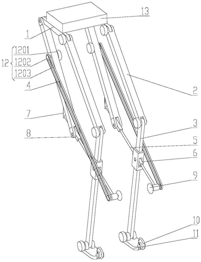
[0022] Such as image 3 and Figure 4 , using the six-bar mechanism of the legged robot for the biped robot, including two sets of six-bar mechanisms for the legged robot and a set of connecting parts 13, fixing the six-bar mechanism for the legged robot to the connecting parts 13, the bipedal robot can be mutually transformed in the bipedal and four-wheeled forms as required, which improves the adaptability of the robot. The specific process is as follows: the thigh bar 2 swings relative to the hip bar 1, so that image 3 As shown, the obtuse angle between the thigh rod 2 and the hip rod 1 decreases, and the calf rod 3 swings relative to the thigh rod 2, so that the obtuse angle between the calf rod 3 and the thigh rod 2 decreases, thus driving the upper passive rod 4 and the lower passive rod 5 Rotate around the rotating shaft of the upper passive rod 4 and the hip rod 1 to realize the deformation of the six-bar mechanism and the ground contact of the driving wheel 9; at t...
PUM
 Abstract
Description
Claims
Application Information
 - R&D
- Intellectual Property
- Life Sciences
- Materials
- Tech Scout
- Unparalleled Data Quality
- Higher Quality Content
- 60% Fewer Hallucinations
Browse by: Latest US Patents, China's latest patents, Technical Efficacy Thesaurus, Application Domain, Technology Topic, Popular Technical Reports.
© 2025 PatSnap. All rights reserved.Legal|Privacy policy|Modern Slavery Act Transparency Statement|Sitemap|About US| Contact US: help@patsnap.com