Washing system and method for tail gas of blower cooling tank area

A tail gas scrubbing system and tail gas technology are applied in separation methods, chemical instruments and methods, and dispersed particle separation, etc., which can solve problems such as difficult recovery of tail gas in tank areas, negative pressure gas pipelines, increased difficulty of tail gas recovery, and lack of tail gas recovery systems. Achieve the effect of meeting the requirements of environmental protection situation and reducing the occupational hazard risk of employees

Inactive Publication Date: 2021-01-29
鞍钢化学科技有限公司
View PDF8 Cites 1 Cited by
  • Summary
  • Abstract
  • Description
  • Claims
  • Application Information

AI Technical Summary

Problems solved by technology

More than 25 oil tanks, including mechanized ammonia water clarification tanks, circulating ammonia water tanks, and residual ammonia water tanks, lack an effective exhaust gas recovery system, and the exhaust gas from the oil tank release pipe is directly discharged, which seriously threatens the occupational health of employees and is difficult to meet the requirements of the current environmental protection situation.
[0003] At present, the tail gas of the drum cooling process is generally recovered to the negative pressure gas pipeline of this process. In order to meet the operation requirements such as oil tank pouring, it is inevitable to mix air in the tail gas of the tank area. pipes, only by washing
In addition, the selection of exhaust gas cleaning liquid is very important. On the one hand, the recyclability of the cleaning liquid must be considered, and on the other hand, the cleaning effect must be considered, which greatly increases the difficulty of exhaust gas recovery.

Method used


Image

  • Washing system and method for tail gas of blower cooling tank area

Examples


Embodiment Construction

[0028] The specific embodiment of the present invention will be further described below in conjunction with accompanying drawing:

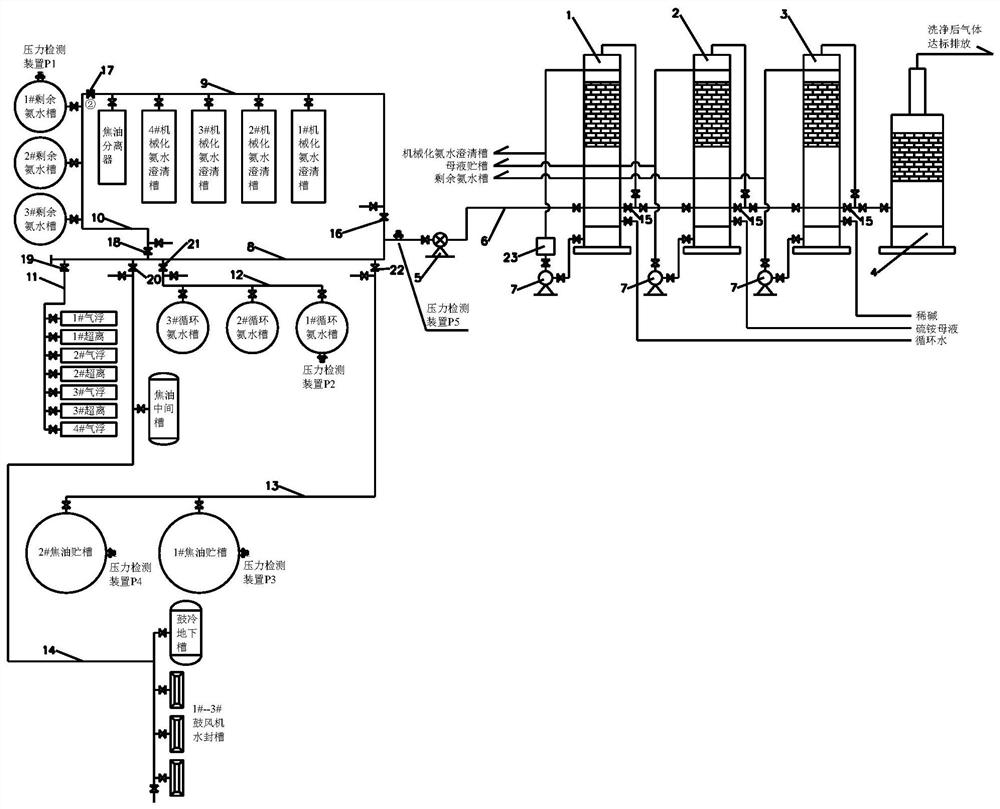
[0029] Such as figure 1 As shown, a tail gas washing system in the drum cold tank area includes a water washing tower 1, an acid washing tower 2, an alkali washing tower 3, an activated carbon adsorption tower 4, a fan 5 and an tail gas pipeline.

[0030] The water washing tower 1, the acid washing tower 2, the alkali washing tower 3 and the activated carbon adsorption tower 4 are connected in series through pipelines in sequence, and after being connected in series, they are connected to the tail gas pipeline through the first connecting pipe 6, and the fan is installed on the first connecting pipe 6. The water washing tower 1, the pickling tower 2, and the alkali washing tower 3 all contain two spraying liquid pumps 7 and auxiliary spraying and external discharge process pipes and valves.

[0031] The water washing tower 1 uses the water in the...


PUM


Abstract

The invention relates to the technical field of coking tail gas treatment, in particular to a washing system and method for tail gas of a blower cooling tank area. The system comprises a water washingtower, an acid washing tower, an alkaline washing tower, an activated carbon adsorption tower, a fan and a tail gas pipeline, wherein the water washing tower, the acid washing tower, the alkaline washing tower and the activated carbon adsorption tower are connected in series through pipelines and then connected with the tail gas pipeline through a first connecting pipe, and the fan is mounted onthe first connecting pipe; and the tail gas pipeline comprises a main tail gas pipe and first to sixth branch tail gas pipes, the first branch tail gas pipe is connected with a mechanical ammonia water clarification tank and a tar separator, the second branch tail gas pipe is connected with a residual ammonia water tank, the third branch tail gas pipe is connected with a tar intermediate tank, a super centrifuge and an air floatation tar remover, the fourth branch tail gas pipe is connected with a circulating ammonia water tank, the fifth branch tail gas pipe is connected with a tar storage tank, and the sixth branch tail gas pipe is connected with a blower cooling underground tank and a blower water seal tank. According to the invention, the process requirements of a drum condensation tank area are met, and the purpose of zero emission of tail gas in the tank area of a blower cooling procedure is achieved.

Description

technical field [0001] The invention relates to the technical field of coking tail gas treatment, in particular to a tail gas washing system and method in a drum cooling tank area. Background technique [0002] The blast condensation process in the recovery operation area of ​​the coking plant is mainly responsible for cleaning and cooling gas, gas transportation, establishing the balance of ammonia water with coking and producing crude tar. Due to the lack of an effective exhaust gas recovery system in the mechanized ammonia water clarification tank, circulating ammonia water tank, and residual ammonia water tank, more than 25 oil tanks in the process, the exhaust gas of the oil tank release pipe is discharged directly, which seriously threatens the occupational health of the employees and is difficult to meet the requirements of the current environmental protection situation. [0003] At present, the tail gas of the drum cooling process is generally recovered to the negati...

Claims


Application Information

Patent Timeline
Patent Type & Authority Applications(China)
IPC IPC(8): B01D53/78B01D53/18B01D53/04
CPCB01D53/78B01D53/18B01D53/04B01D2253/102
Inventor 范壮郭方明张欣于智晓
Owner 鞍钢化学科技有限公司
Why Eureka
Try Eureka