
Rotor structure and generator

A technology of rotor structure and rotor core, applied in the direction of magnetic circuit shape/style/structure, electric components, electrical components, etc., can solve problems such as difficult installation, difficult processing, and poor heat dissipation

Pending Publication Date: 2021-01-26
JIANGXI QINGHUA TAIHAO SANBO ELECTRICAL MACHINE
View PDF0 Cites 0 Cited by
  • Summary
  • Abstract
  • Description
  • Claims
  • Application Information

AI Technical Summary

Problems solved by technology

[0003] The purpose of the present invention includes providing a rotor structure, which can solve the technical problems of difficult installation, difficult processing and poor heat dissipation performance in the prior art

Method used


Image

  • Rotor structure and generator
  • Rotor structure and generator
  • Rotor structure and generator

Examples


Embodiment Construction

[0033] In order to make the purpose, technical solutions and advantages of the embodiments of the present invention clearer, the technical solutions in the embodiments of the present invention will be clearly and completely described below in conjunction with the drawings in the embodiments of the present invention. Obviously, the described embodiments It is a part of embodiments of the present invention, but not all embodiments. The components of the embodiments of the invention generally described and illustrated in the figures herein may be arranged and designed in a variety of different configurations.

[0034] Accordingly, the following detailed description of the embodiments of the invention provided in the accompanying drawings is not intended to limit the scope of the claimed invention, but merely represents selected embodiments of the invention. Based on the embodiments of the present invention, all other embodiments obtained by persons of ordinary skill in the art wi...


PUM


Abstract

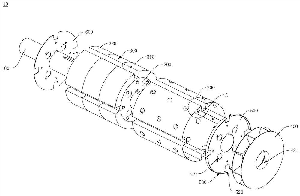
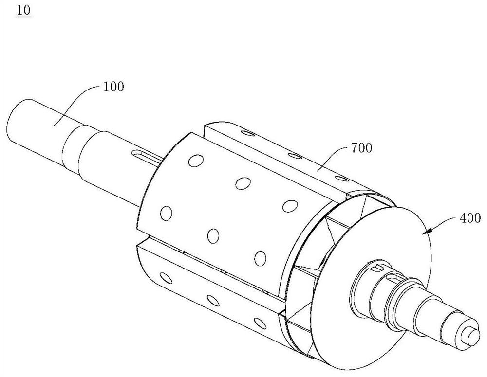
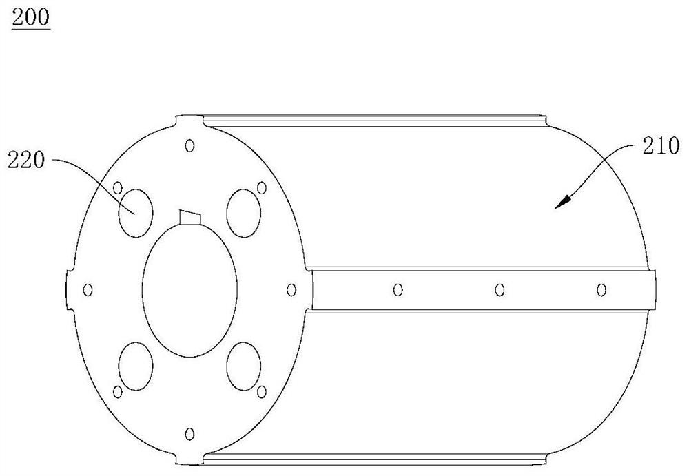
The invention provides a rotor structure and a generator, and relates to the technical field of generators. The rotor structure comprises a rotating shaft, a rotor core, an air guide structure and a plurality of magnets. The rotor core is installed on the rotating shaft, a first through hole is formed in the rotor core, and the first through hole penetrates through the two end faces of the rotor core in the axial direction of the rotor core. The plurality of magnets are arranged in the outer circumference of the rotor core at intervals, and a gap is formed between every two adjacent magnets. The air guide structure comprises a first end plate and a fan blade structure. The first end plate is connected to one axial side of the fan blade structure, and the first end plate is arranged betweenthe fan blade structure and the rotor core and covers the gap. The first end plate is provided with a second through hole used for air suction of the fan blade structure, and the second through holeis communicated with the first through hole. The invention further provides a generator which adopts the rotor structure. The rotor structure and the generator provided by the invention can solve thetechnical problems of difficult installation, difficult processing and poor heat dissipation performance in the prior art.

Description

technical field [0001] The invention relates to the technical field of generators, in particular to a rotor structure and a generator. Background technique [0002] Generally speaking, the rotor structure of a permanent magnet generator is generally embedded with magnetic steel radially evenly distributed on the rotor yoke, and the rotor yoke is formed by lamination of punched sheets. On the one hand, after the rotor yoke is embedded with magnetic steel, the teeth of the rotor yoke On the other hand, the magnetic steel has strong magnetism, and it is not easy to align when it is embedded in the rotor yoke. The generator mainly relies on the air gap for heat dissipation, and the heat dissipation performance is not good. Contents of the invention [0003] The purpose of the present invention includes providing a rotor structure, which can solve the technical problems of difficult installation, difficult processing and poor heat dissipation performance in the prior art. [...

Claims


Application Information

Patent Timeline
IPC IPC(8): H02K1/27H02K1/32H02K9/06
CPCH02K1/278H02K1/32H02K9/06
Inventor 万亚玲杨家国罗蓉琅邓鹏
Owner JIANGXI QINGHUA TAIHAO SANBO ELECTRICAL MACHINE
Learn More