Automobile shock absorber

A technology of automobile shock absorption and inner cylinder, which is applied in the direction of shock absorber, spring/shock absorber, shock absorber, etc., can solve the problem that the damping effect is limited, the compression damping force cannot be formed, and the vehicle's handling, comfort and performance are affected. Safety and reliability and other issues, to achieve the effect of improving shock absorption performance, improving impact phenomenon, and improving driving comfort

Active Publication Date: 2022-07-26
宿州学院
View PDF0 Cites 0 Cited by
  • Summary
  • Abstract
  • Description
  • Claims
  • Application Information

AI Technical Summary

Problems solved by technology

Existing shock absorbers generally include an inner cylinder, an outer cylinder and a damping spring; the inner cylinder is generally sleeved on the outer cylinder through a piston, and the space opposite the outer cylinder and the piston is filled with hydraulic oil. When the inner cylinder reciprocates, the hydraulic oil Flow is formed in this space and in the inner cylinder, which plays the role of lubrication and limited liquid damping. In fact, because the diameter difference between the inner cylinder and the outer cylinder is not large, the damping effect is also extremely limited, and no effective compression damping force can be formed. , on a slightly larger uneven road surface, the shock absorber will bottom out, which will seriously affect the handling, comfort and safety reliability of the vehicle

Method used


Image

  • Automobile shock absorber
  • Automobile shock absorber

Examples


Embodiment Construction

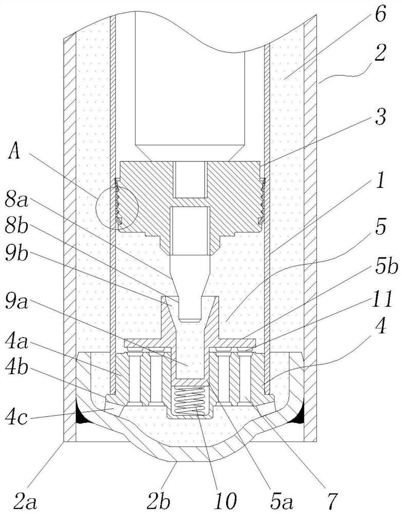
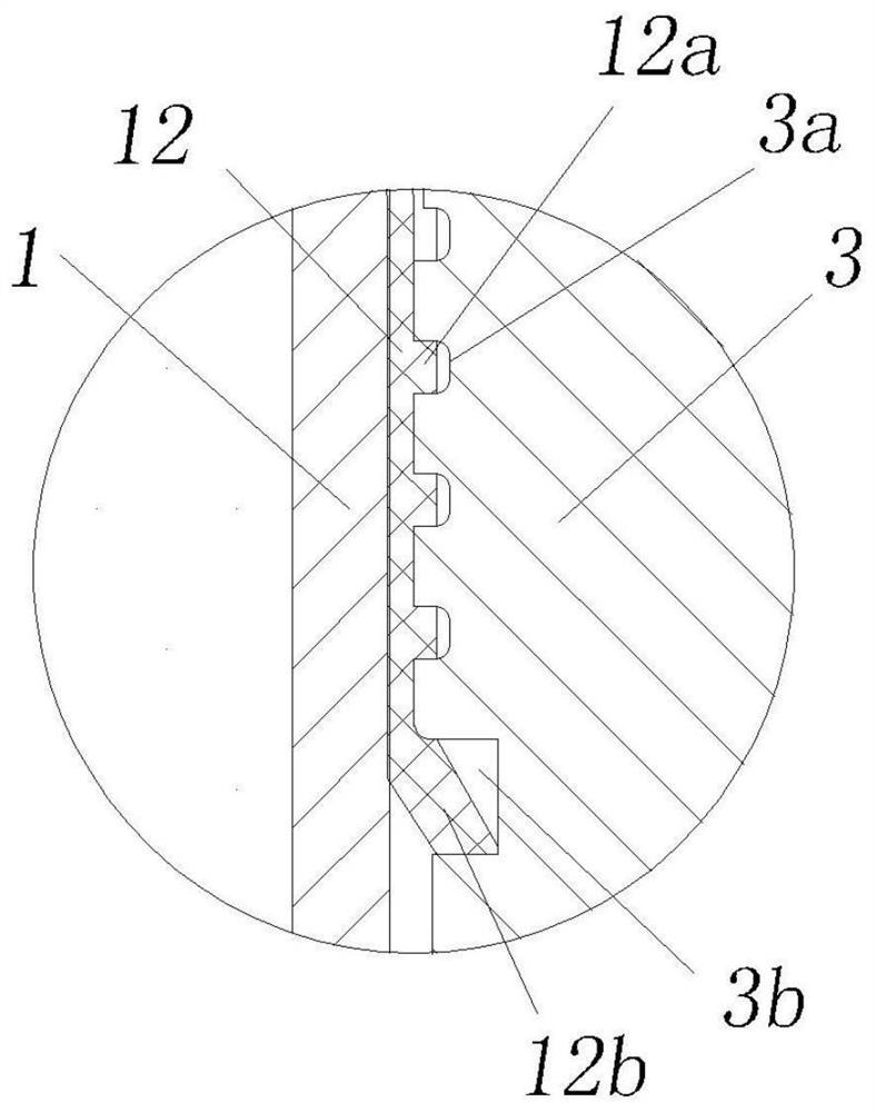
[0020] figure 1 It is a schematic diagram of the overall structure of the shock absorber; figure 2 Schematic diagram of the enlarged structure of point A of the shock absorber;

[0021] In this embodiment, an automobile shock absorption device is provided, including an outer cylinder 2 with an open top, an inner cylinder 1 sleeved inside the outer cylinder and open at both ends, a piston 3 slidingly sealed in the inner cylinder, and sealed in the inner cylinder The flow passage 4 and the valve cover 5 at the bottom have an annular liquid cavity 6 between the inner cylinder and the outer cylinder, and a damping hole 7 connecting the inner cylinder cavity and the annular liquid cavity is opened on the flow passage assembly, so The valve cover can be slid up and down on the overflow member to close or open the damping hole, and the bottom of the piston is connected with an anti-bottom member 8. A non-contact downward force causes the valve cover to close the orifice preventing...


PUM


Abstract

The invention discloses a shock absorbing device for automobiles, comprising an outer cylinder, an inner cylinder, a piston slidingly sealed in the inner cylinder, a flow passage member sealed at the bottom of the inner cylinder, and a valve cover. an annular liquid cavity, the flow-over component is provided with a damping hole that communicates the inner cylinder cavity with the annular liquid cavity, the valve cover can be slid up and down on the flow-over member to close or open the orifice, and the bottom of the piston An anti-bottoming piece is connected, and the anti-bottoming piece has a non-contact downward force on the valve cover during the process of descending with the piston and approaching the valve cover, so that the valve cover closes the damping hole to prevent the further descending of the piston; During the downward movement of the piston rod, the non-contact downward force is exerted on the valve cover through the anti-bottoming element, so that the valve cover is sealed in the damping hole, the damping fluid stops flowing from the inner cylinder to the annular liquid chamber, and the piston stops downward, preventing the piston rod from descending. Bottom out to avoid shock bottoming when driving on rougher surfaces.

Description

technical field [0001] The invention belongs to the technical field of motor vehicles, and relates to an automobile shock absorbing device. Background technique [0002] The shock absorber is a necessary part of the vehicle. The structure affects the handling and comfort of the whole vehicle, and whether the performance is stable and reliable is directly related to the safety, reliability, comfort and handling of the whole vehicle. Existing shock absorbers generally include an inner cylinder, an outer cylinder and a shock-absorbing spring; the inner cylinder is generally sleeved on the outer cylinder through the piston, and the space opposite the outer cylinder and the piston downward is filled with hydraulic oil. Flow is formed in this space and in the inner cylinder, which plays the role of lubrication and limited liquid damping. In fact, because the diameters of the inner cylinder and the outer cylinder are not much different, the damping effect is extremely limited, and ...

Claims


Application Information

Patent Timeline
Patent Type & Authority Patents(China)
IPC IPC(8): F16F9/18F16F9/32F16F9/34F16F9/56
CPCF16F9/185F16F9/3207F16F9/34F16F9/3235F16F9/3257F16F9/56
Inventor 王楠刘浩李敏刘燕杨权
Owner 宿州学院
Why Eureka
Try Eureka