
A deep slab load in-situ test method for ultra-thick backfill soil

A deep plate load, in-situ testing technology, applied in the field of foundation soil survey, construction, infrastructure engineering, etc., can solve the problem of poor soil consolidation, deformation of the slenderness ratio of the force transmission column, poor stability of backfill soil, etc. problem, to achieve the effect of improving precision and accuracy

Active Publication Date: 2022-04-08
POWERCHINA BEIJING ENG
View PDF5 Cites 0 Cited by
  • Summary
  • Abstract
  • Description
  • Claims
  • Application Information

AI Technical Summary

Problems solved by technology

[0004] The in-situ test method of deep plate load commonly used at present is greatly affected by the depth and stability of lithology and soil layers, and at the same time, the deformation and bending of the dowel bar and the displacement and deformation of the reaction force system during the loading process affect the accuracy of the test data. Accuracy, the general test depth is up to about 20m. In the area of ​​super-thick backfill soil, the stability of the backfill soil is poor, the degree of soil consolidation is poor (generally under-consolidated soil), the soil structure is loose, and the ground anchor provides The reaction force is not enough to meet the requirements of the test and the spiral plate load test is difficult to reach the required depth of the test. At the same time, the deep plate load in-situ test method is difficult to realize when the test depth is large, and the conventional manual digging hole (vertical wall) and the force transmission column The increase of the slenderness ratio will produce a large deformation, seriously affecting the accuracy of the test

Method used


Image

  • A deep slab load in-situ test method for ultra-thick backfill soil
  • A deep slab load in-situ test method for ultra-thick backfill soil
  • A deep slab load in-situ test method for ultra-thick backfill soil

Examples


Embodiment Construction

[0026] The following will clearly and completely describe the technical solutions in the embodiments of the present invention in conjunction with the accompanying drawings in the embodiments of the present invention; obviously, the described embodiments are only part of the embodiments of the present invention, not all embodiments, based on The embodiments of the present invention and all other embodiments obtained by persons of ordinary skill in the art without making creative efforts belong to the protection scope of the present invention.

[0027] In the description of the present invention, it should be noted that the orientations or positional relationships indicated by the terms "upper", "lower", "inner", "outer", "top / bottom" etc. are based on the orientations shown in the drawings Or positional relationship is only for the convenience of describing the present invention and simplifying the description, but does not indicate or imply that the device or element referred t...


PUM


Abstract

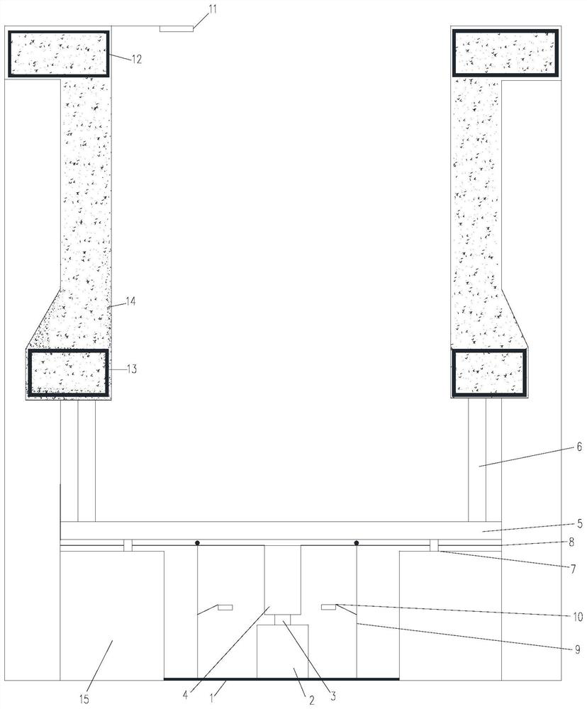
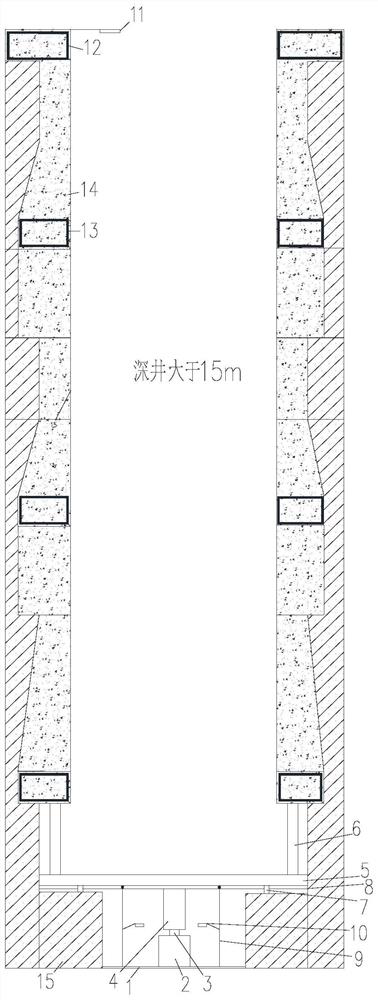
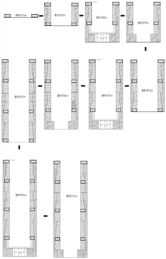
The invention discloses a method for in-situ testing of deep plate loads for super-thick layer backfill soil. The enlarged diameter in the well is formed through an artificial deep well, which is used for placing load test equipment, and a reinforced concrete ring is designed on the top surface of the enlarged part of the well diameter. Beam, using ring beam gravity and ring beam upper retaining wall side wall and soil friction as the reaction device for deep plate load in situ test, so that the reaction force of deep plate load in situ test is clear and the reaction force and loading device are stable , a space with a diameter of 1m is formed 80cm below the enlarged part, which is used to place pressure plates, jacks, displacement gauges, force transmission columns, etc. and form a semi-infinite space for the soil, which can project the stress state inside the soil and is not affected by rocks. Effectively control the elastic deformation and bending deformation of the force transmission column during the loading process, and adopt a variety of test and monitoring methods to improve the accuracy and accuracy of the test data.

Description

technical field [0001] The invention belongs to the field of geotechnical engineering, in particular to an in-situ test method for deep plate loads used for super-thick layer backfill soil. Background technique [0002] In the development and application of geotechnical engineering, in the design and testing of foundations for elevation, super-elevation structures, heavy industrial plants, bridges, etc., the standard value of foundation bearing capacity provided by the load test or the pile tip soil should be used. The standard value of bearing capacity, due to the deep burial of the foundation and the large load, has strict requirements on the foundation, and the conventional load test method cannot reflect the authenticity of the mechanical properties of the deep foundation soil, so other in-situ test methods are commonly used: such as static penetration testing and dynamic penetration testing , side pressure test, standard penetration test and other methods give empirical...

Claims


Application Information

Patent Timeline
Patent Type & Authority Patents(China)
IPC IPC(8): E02D1/00
CPCE02D1/00
Inventor 齐本亮朱敏郝伟齐志诚李少朋朱爱农杨明群
Owner POWERCHINA BEIJING ENG
Learn More