
Embossing device for artificial leather production

An artificial leather and embossing technology, applied in textiles, papermaking, textile material cutting and other directions, can solve problems such as unreachable hand feel and elasticity, limited area of ​​embossed panels, increased production costs, etc., to reduce labor production costs, The effect of better use flexibility and stronger use flexibility

Pending Publication Date: 2021-01-26
QINGYUAN QILI SYNTHETIC LEATHER
View PDF0 Cites 0 Cited by
  • Summary
  • Abstract
  • Description
  • Claims
  • Application Information

AI Technical Summary

Problems solved by technology

[0002] Artificial leather is made of various formulations of PVC and PU foamed or coated on a woven or non-woven fabric base. It can be processed according to different strengths, colors, luster, patterns, etc. , has the characteristics of a wide variety of designs and colors, good waterproof performance, neat edges, high utilization rate and cheaper price than genuine leather, but most of the artificial leather, its feel and elasticity can not achieve the effect of genuine leather; Air bubble holes, cloth base or surface film and dry man-made fibers must be pressed into patterns by embossing machines during industrial processing and production.
[0003] The existing technology has the following problems: when the equipment is used, the pattern is formed by stamping, and the embossed panel area of ​​the equipment is limited, and the artificial leather of the specified specification can only be embossed each time. The current solution is to cut the artificial leather in advance by the workers. Real-time operation places the artificial leather under the stamping panel, but this solution requires the equipment to be stopped before operation, which will take up more production time and cause increased production costs

Method used


Image

  • Embossing device for artificial leather production
  • Embossing device for artificial leather production
  • Embossing device for artificial leather production

Examples


Embodiment 1

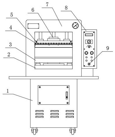
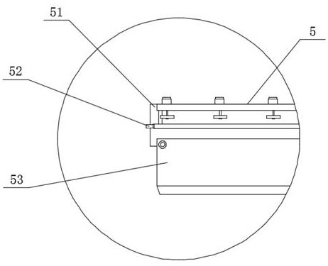
[0026] Such as Figure 1-2 As shown, an embossing device for the production of artificial leather includes a body 1 and a stamping table 7, the top end of the body 1 is connected with a stamping table 7, and the upper end of the front end of the stamping table 7 is connected with a connecting rod 6 , the bottom end surface of the connecting rod 6 is connected with the stamping panel 4 by bolts, the cutting knife group 5 is connected to the lower position of the front end surface of the stamping panel 4, the workbench 3 is arranged below the cutting knife group 5, and the bottom of the workbench 3 The end face is connected with a buffer table 2 by bolts, and the right side of the buffer table 2 is provided with a control box 8 on the right end face of the stamping table 7, and a power switch 9 is connected to the lower end of the front end face of the control box 8, and a cutting knife set 5 It includes a fixed knife plate 51 , a cleaning plate 52 and a cutting blade 53 , a cle...

Embodiment 2

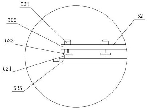
[0029] Such as Figure 1-3 As shown, an embossing device for the production of artificial leather includes a body 1 and a stamping table 7, the top end of the body 1 is connected with a stamping table 7, and the upper end of the front end of the stamping table 7 is connected with a connecting rod 6 , the bottom end surface of the connecting rod 6 is connected with the stamping panel 4 by bolts, the cutting knife group 5 is connected to the lower position of the front end surface of the stamping panel 4, the workbench 3 is arranged below the cutting knife group 5, and the bottom of the workbench 3 The end face is connected with a buffer table 2 by bolts, and the right side of the buffer table 2 is provided with a control box 8 on the right end face of the stamping table 7, and a power switch 9 is connected to the lower end of the front end face of the control box 8, and a cutting knife set 5 Comprising a fixed knife plate 51, a cleaning plate 52 and a cutting blade 53, a cleani...

Embodiment 3

[0032] Such as Figure 1-4 As shown, an embossing device for the production of artificial leather includes a body 1 and a stamping table 7, the top end of the body 1 is connected with a stamping table 7, and the upper end of the front end of the stamping table 7 is connected with a connecting rod 6 , the bottom end surface of the connecting rod 6 is connected with the stamping panel 4 by bolts, the cutting knife group 5 is connected to the lower position of the front end surface of the stamping panel 4, the workbench 3 is arranged below the cutting knife group 5, and the bottom of the workbench 3 The end face is connected with a buffer table 2 by bolts, and the right side of the buffer table 2 is provided with a control box 8 on the right end face of the stamping table 7, and a power switch 9 is connected to the lower end of the front end face of the control box 8, and a cutting knife set 5 It includes a fixed knife plate 51, a cleaning plate 52 and a cutting blade 53, a clean...


PUM


Abstract

The invention provides an embossing device for artificial leather production. The embossing device comprises a machine body and a stamping table; the stamping table is connected to the end face of thetop end of the machine body; a connecting rod is connected to the upper portion of the inner side of the end face of the front end of the stamping table in a penetrating mode; and a stamping panel isconnected to the end face of the bottom end of the connecting rod through bolts. During use, a cutter set can be used for cutting an exposed part of artificial leather without influencing the normalmovement of equipment, the separated artificial leather can be taken out after cutting is finished, and then the embossed artificial leather is subjected to position stretching and repeated operation.By means of the mode, equipment does not need to be shut down for tailoring work, tailoring work does not need to be carried out in advance, embossed artificial leather is separated while stamping iscarried out, and meanwhile, repeated operation can be carried out, so that extremely high use flexibility is achieved, and the problem of labor production cost caused by shutting down the equipment and tailoring materials in advance can be reduced to a certain extent.

Description

technical field [0001] The invention relates to the field of artificial leather, in particular to an embossing device for the production of artificial leather. Background technique [0002] Artificial leather is made of various formulations of PVC and PU foamed or coated on a woven or non-woven fabric base. It can be processed according to different strengths, colors, luster, patterns, etc. , has the characteristics of a wide variety of designs and colors, good waterproof performance, neat edges, high utilization rate and cheaper price than genuine leather, but most of the artificial leather, its feel and elasticity cannot achieve the effect of genuine leather; Air bubble holes, cloth base or surface film and dry man-made fibers must be pressed into patterns by embossing machines during industrial processing and production. [0003] The existing technology has the following problems: when the equipment is used, the pattern is formed by stamping, and the embossed panel are...

Claims


Application Information

Patent Timeline
IPC IPC(8): D06N3/00D06H7/00
CPCD06H7/00D06N3/0077
Inventor 刘爱明罗志清郑重郑然梁勇劲戴小平
Owner QINGYUAN QILI SYNTHETIC LEATHER
Learn More