


Quick Research
Generate reliable direction feasibility study reports for your R&D in just a few steps.

Technical Q&A
Discover and master advanced knowledge NOW. Basics, ideas, possibilities, all at once.

Find Solutions
As an expert in R&D theories, this can generate solutions to your technical problems instantly.

Evaluate Feasibility
Analyze your overall solution with one click, know your potential R&D risks in advance.

Monitor Landscape
Get weekly tech updates, stay abreast of the latest tech innovations and key insights.
Smart home transfer device
A transfer device and smart home technology, applied in the direction of transportation and packaging, multi-axis trolleys, trolley accessories, etc., can solve the problems of large manpower consumption, large manpower consumption, and failure to use normally, so as to reduce height consumption, improve work efficiency, The effect of increasing the burden
- Summary
- Abstract
- Description
- Claims
- Application Information
AI Technical Summary
Problems solved by technology
Method used
Image


Examples
Embodiment 1
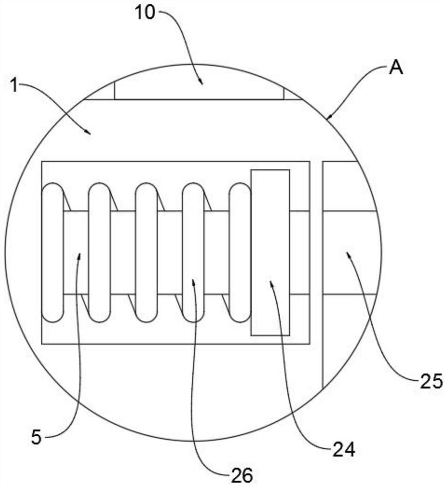
[0024] Example 1, such as Figure 1-5 As shown, the present invention provides a smart home transfer device, including a base 1, the inside of the base 1 is rotatably connected to a swing plate 2 through a first rotating shaft, a pedal 3 is welded on the left side of the swing plate 2, and the swing plate 2 is far away from the pedal 3 One end of the first connecting rod 4 is rotatably connected with the first bearing, the left side of the base 1 slides through the second connecting rod 5, and the end of the second connecting rod 5 away from the pull ring 6 is welded with a second limiting plate 24. The second limiting plate 24 is welded with a clamping rod 25 away from the side of the second connecting rod 5, the outer surface of the second connecting rod 5 is sleeved with a first spring 26, and the inside of the base 1 is provided with a spring 26 corresponding to the second limiting plate 24. Adapted limit groove, the right end of the first spring 26 is welded on the left s...
Embodiment 2
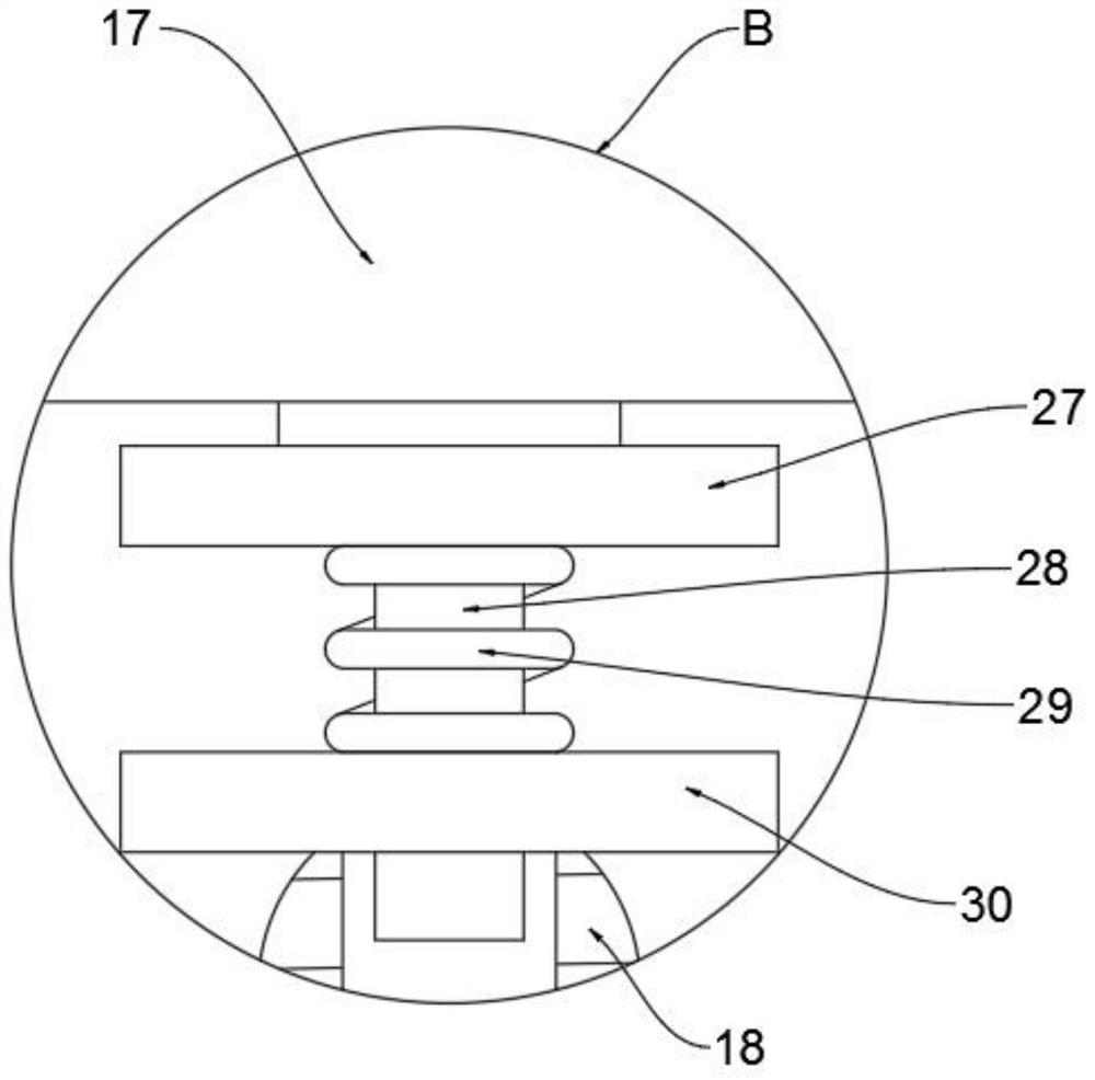
[0026] Example 2, such as figure 1 and Figure 4 As shown, the outer surface of the third connecting rod 10 away from the base 1 is rotatably connected with a swivel 11 through a third bearing, the bottom end of the push rod 12 is welded with a second threaded rod 31, and the top of the swivel 11 is provided with a second screw thread. There is a threaded hole matching the thread on the rod 31 , and an insertion hole matching the second threaded rod 31 is opened on the top end of the third connecting rod 10 .
[0027] The effect achieved by the whole embodiment 2 is, before moving, at first adjust according to the height of the observing staff, so that the push rod 12 reaches the corresponding height within the limited height, and by rotating the swivel 11, it is positioned at the first The second threaded rod 31 inside the three connecting rods 10 moves. When rotating the swivel 11, pull the push rod 12 with a little force to make the second threaded rod 31 at the bottom of ...
Embodiment 3
[0028] Example 3, such as figure 1 and Figure 5 As shown, the top of the base 1 near the edge of the right side is connected with a baffle 15 through a third rotating shaft, the top of the placement plate 13 and the top of the baffle 15 are fixedly equipped with a buckle 14, and the baffle 15 is close to the side of the placement plate 13. One side is rotatably connected to the roller 32 through the fourth rotating shaft, and the side of the baffle plate 15 close to the placement plate 13 is provided with a mounting groove compatible with the roller 32 .
[0029] The effect achieved by the whole embodiment 3 is that when in use, firstly, the catch 14 fixedly installed on the top of the placement plate 13 and the top of the baffle plate 15 is opened to separate the baffle plate 15 from the placement plate 13, and then the baffle plate 15 is opened. , the baffle plate 15 is rotated and the side of the baffle plate 15 away from the placement plate 13 is in contact with the grou...
PUM
 Abstract
Description
Claims
Application Information
 - R&D Engineer
- R&D Manager
- IP Professional
- Industry Leading Data Capabilities
- Powerful AI technology
- Patent DNA Extraction
Browse by: Latest US Patents, China's latest patents, Technical Efficacy Thesaurus, Application Domain, Technology Topic, Popular Technical Reports.
© 2024 PatSnap. All rights reserved.Legal|Privacy policy|Modern Slavery Act Transparency Statement|Sitemap|About US| Contact US: help@patsnap.com