Wind-driven window wiper for automobile rearview mirror
A technology for automotive rearview mirrors and wipers, which is applied in vehicle maintenance, vehicle parts, vehicle cleaning, etc., can solve problems such as dangerous accidents, inconvenient operation, and inability to see vehicles clearly, so as to avoid dangerous accidents and facilitate operation. Effect
- Summary
- Abstract
- Description
- Claims
- Application Information
AI Technical Summary
Problems solved by technology
Method used
Image
Examples
Embodiment 1
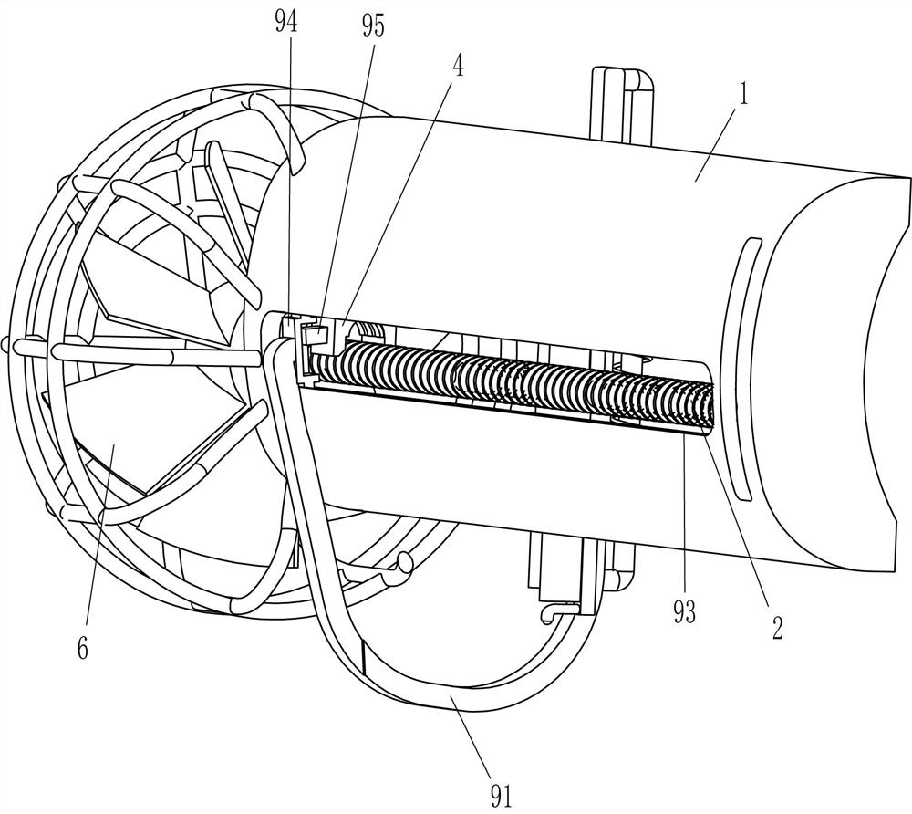
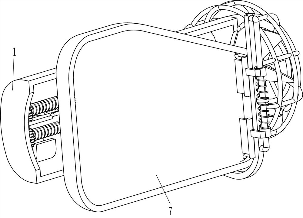
[0022] A wind-driven wiper for a car rearview mirror, such as Figure 1-Figure 3 As shown, it includes a frame body 1, a screw rod 2, a gear 3, a two-way nut 4, a magnet 5, a fan blade 6, an elastic rod 8 and a scraper mechanism 9, and the upper and lower symmetrical rotation between the middle parts of the left and right sides of the frame body 1 is designed. There is a screw 2, the thread of the screw 2 on the upper and lower sides is opposite, the left side of the screw 2 is fixedly connected with a gear 3, and the two gears 3 mesh, and there is a two-way nut 4 sliding between the two screw 2, and the two-way nut 4 cooperates with the screw 2 A magnet 5 is fixedly connected to the left lower part and the right upper part of the rear side of the frame body 1. The magnet 5 cooperates with the two-way nut 4. The fan blade 6 is fixedly connected to the right end of the lower screw rod 2. Between the left and right sides of the frame body 1 Two elastic rods 8 are provided, and t...
Embodiment 2
[0027] On the basis of Example 1, such as figure 2 As shown, it also includes a wiper mechanism 10. The wiper mechanism 10 includes an n-shaped rod 101, a sliding sleeve 102, a spring 103, a second scraper 104 and a contact rod 105, and the upper part of the outer front side of the u-shaped rod 91 is fixed with The n-type rod 101 is provided with two sliding sleeves 102 slidingly on the n-type rod 101. The inner surfaces of the upper and lower sides of the sliding sleeves 102 are fixedly connected with springs 103. Set on the n-shaped rod 101, the left side of the sliding sleeve 102 is fixedly connected with the second scraper 104, the upper part of the inner front side of the upper second scraper 104 and the lower part of the inner front side of the lower second scraper 104 are fixed with Contact rod 105 .
[0028] Initially, the spring 103 is in a compressed state. When the car is running, the fan blade 6 drives the two-way nut 4 to move left and right through the rotation...
Embodiment 3
[0030] On the basis of embodiment 1 and embodiment 2, such as figure 2 and Figure 4 As shown, a protective cover 11 is also included, and the right side of the frame body 1 is fixedly connected with the protective cover 11 , and the fan blade 6 is located in the protective cover 11 .
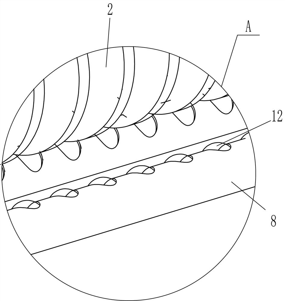
[0031] Balls 12 are also included, and balls 12 are evenly arranged on the inner surfaces of the two elastic rods 8 .
[0032]When the car is running, the fan blade 6 starts to rotate, and the protective cover 11 can prevent foreign garbage or sundries from entering the fan blade 6, so that it can prevent the fan blade 6 from stopping to rotate due to foreign garbage or sundries.
[0033] When bidirectional nut 4 moved left and right, bidirectional nut 4 was in contact with two elastic rods 8, because of the effect of ball 12, bidirectional nut 4 moved left and right better on two screw rods 2, like this, can make bidirectional nut 4 move more smooth.
PUM
 Abstract
Description
Claims
Application Information
 - R&D
- Intellectual Property
- Life Sciences
- Materials
- Tech Scout
- Unparalleled Data Quality
- Higher Quality Content
- 60% Fewer Hallucinations
Browse by: Latest US Patents, China's latest patents, Technical Efficacy Thesaurus, Application Domain, Technology Topic, Popular Technical Reports.
© 2025 PatSnap. All rights reserved.Legal|Privacy policy|Modern Slavery Act Transparency Statement|Sitemap|About US| Contact US: help@patsnap.com


