Reinforcing bar binding machine

A strapping machine and steel bar technology, which is applied to the parts, structural elements, building components, etc. of the strapping machine, can solve the problems of high height, complex structure, corrosion of steel bars, etc., and achieve simple structure, formation of smooth circles, restraint of steel bars The effect of corrosion

Inactive Publication Date: 2003-10-01
KANZAKI SHOKAI
View PDF1 Cites 1 Cited by
  • Summary
  • Abstract
  • Description
  • Claims
  • Application Information

AI Technical Summary

Problems solved by technology

Therefore, similarly to the above, the height of the twisted part of the traveler becomes high, and at the same time, since the above-mentioned wasted part further spreads on the twisted part, the steel wire is exposed from the concrete, and as a result, the problem of corrosion of steel bars occurs.
[0007] Further, in this steel bar binding machine, various mechanical elements such as motors, various gears, various cams, clutches and rollers are used for the driving mechanism, and the structure is too complicated.

Method used


Image

  • Reinforcing bar binding machine
  • Reinforcing bar binding machine
  • Reinforcing bar binding machine

Examples


Embodiment Construction

[0065] Next, embodiments of the present invention will be described with reference to the drawings.

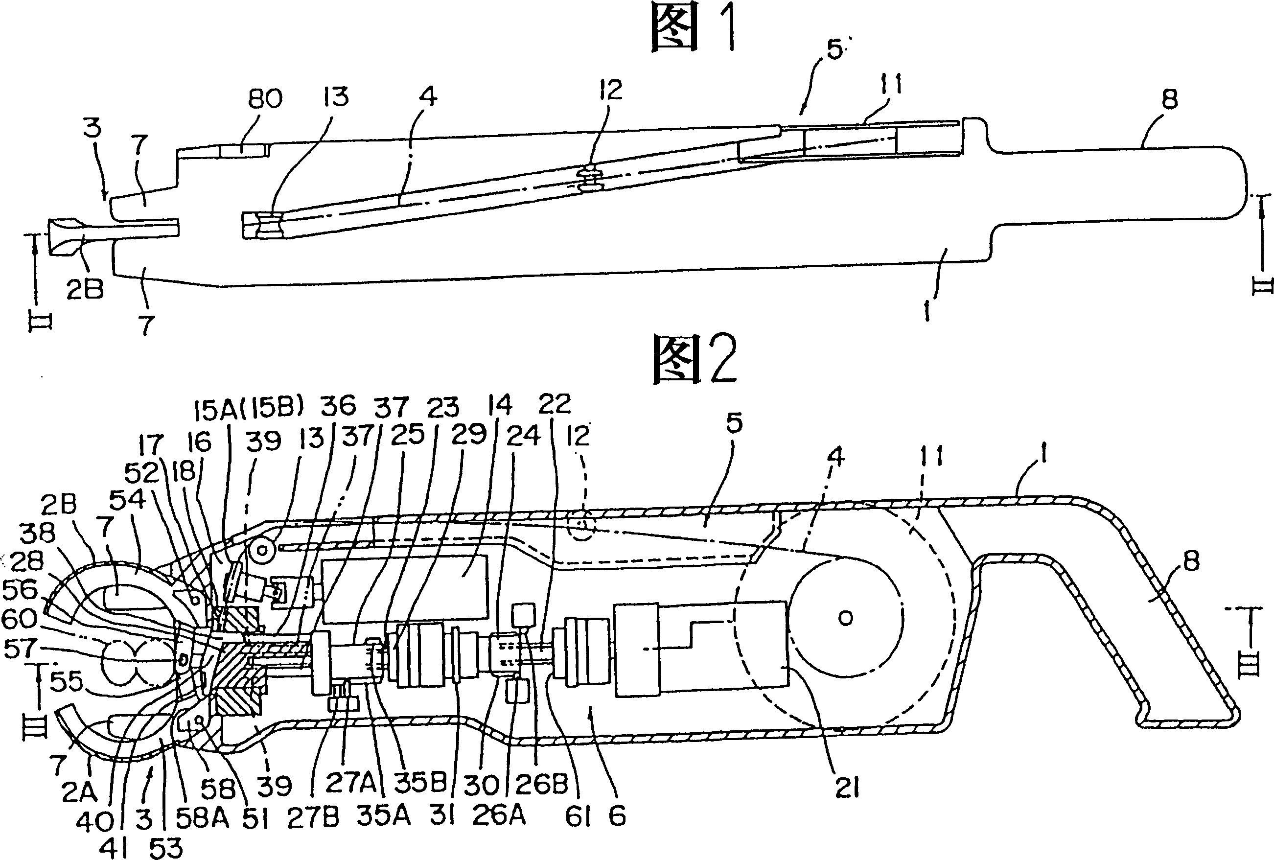
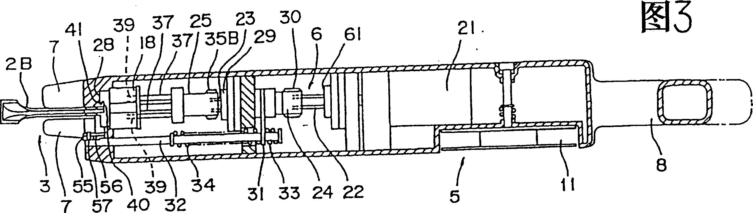
[0066] Fig. 1-3 has shown about the steel bar binding machine of the present invention, and it is provided with the ring forming part 3 of a pair of curved member 2A, 2B that has groove that can be arranged on this main body 1 head can open and close. composition.

[0067] The main body 1 is provided with a wire supply unit 5 that feeds the wire 4 to the loop forming unit 3 and a drive mechanism 6 that cuts the wire 4, opens and closes the bending member, twists the traveler, etc., as will be described in detail below. In addition, at the front of the main body 1, that is, at the left end in FIG. . The extension part 7, in addition to the action of making the steel bar crossing part in the twisted center position, also plays a role in preventing the bending members 2A, 2B from colliding with the steel bar or other things and being damaged.

[0068] The steel wire supply uni...


PUM


Abstract

A steel bar binding machine with a simple structure and a light weight that makes it possible to prevent the steel wires that cause steel bar corrosion from protruding from the concrete by reducing the height of the twisted part of the bead ring. It is composed of a main body 1 and a The loop forming part 3 of a pair of grooved bending members 2A, 2B which is arranged on the head of the main body 1 is composed of the loop forming part 3, and the main body 1 is constituted by being equipped with a steel wire supply part 5 and a driving mechanism 6, wherein the steel wire supply part 5 is in the Surrounding the crossing portion of the steel bar 60, the curved members 2A in closed state, the grooves of 2B are fed into the steel wire 4 to form a loop of the steel wire 4, and the drive mechanism 6 sequentially opens and closes the curved components through a motor 21 to form the above-mentioned loop. Afterwards, the advance and retreat of the cutting knife 36 that cuts the steel wire 4 output to the above-mentioned groove portion, and the advance and retreat and rotation of a pair of strut members 37 that are arranged side by side with intervals in the above-mentioned circle formed by twisting and binding the steel bar 60 by the above-mentioned steel wire 4 .

Description

technical field [0001] The invention relates to a portable steel bar binding machine which uses steel wires to bind the intersections of steel bars arranged vertically and horizontally at the construction site. Background technique [0002] Previously, as a proposal to improve the work of binding steel bars at construction sites, the Figure 29 The steel bar binding machine shown (Japanese Patent Publication No. 5-13223). This steel bar binding machine is provided with a J-shaped ring forming part 102 at the head of the main body 101, and a steel wire reel 103 is provided at the rear part of the main body 101. The ring forming part 102 advances and retreats through a reciprocating drive device 104, and the steel wire 105 is drawn from the steel wire reel. 103 is output through a pair of pinch wheels 107 driven by a motor 106 . Further, the wire 105 is supplied to the loop forming unit 102 through a wire cutting unit 108 driven by an electromagnetic coil not shown in the fig...

Claims


Application Information

Patent Timeline
Patent Type & Authority Patents(China)
IPC IPC(8): E04C5/18E04G21/12
CPCE04G21/122E04G21/123Y10T29/5187
Inventor 汤口贞雄大割聪夫
Owner KANZAKI SHOKAI
Why Eureka
Try Eureka