Linear array push-broom CCD image rapid automatic geometric correction method

A geometric correction and image technology, applied in the field of image processing, can solve problems such as unable to meet actual needs, unable to achieve automatic correction, limitations, etc., to achieve the effect of fast automatic geometric correction

Active Publication Date: 2021-01-22
PLA AIR FORCE AVIATION UNIVERSITY
View PDF2 Cites 1 Cited by
  • Summary
  • Abstract
  • Description
  • Claims
  • Application Information

AI Technical Summary

Problems solved by technology

[0003] Typical geometric correction methods include strict geometric correction and approximate geometric correction, both of which have limitations in some cases and cannot meet actual needs
Strict geometric correction needs to obtain accurate six camera external orientation elements to accurately calculate the parameters of the correction formula and get a good correction result. If the position and attitude sensors on the camera cannot do this, the use of strict geometric correction will be restricted. influences
The parameters of the approximate geometric correction formula are calculated by manually selecting enough control point pairs. It requires manual operation, so the correction efficiency is very low, and its use is limited when there are strict requirements on the correction time, and automatic correction cannot be realized.

Method used


Image

  • Linear array push-broom CCD image rapid automatic geometric correction method
  • Linear array push-broom CCD image rapid automatic geometric correction method
  • Linear array push-broom CCD image rapid automatic geometric correction method

Examples


Embodiment Construction

[0040] The derivation of the mathematical model formula of the linear array push-broom CCD image rapid automatic geometric correction method of the present invention

[0041] The basic principle of this calibration method

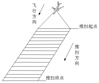
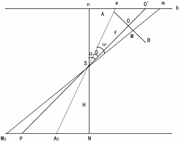
[0042] If the linear array push-broom CCD camera is installed obliquely, the scale of the oblique image along the oblique direction will not be uniform, resulting in deformation, which cannot reflect the positional relationship of the real ground objects. The linear array push-broom CCD camera images a line at every moment, which can be figure 1 Each line of the entire image from the push-broom start point to the push-broom end point is corrected separately to complete the correction of the entire image. The geometric relationship of the linear array push-broom CCD image at a certain moment of imaging is as follows: image 3 As shown, AB represents the linear array push-broom CCD image line at this moment, and ab represents the line in the corresponding o...


PUM


Abstract

The invention discloses a linear array push-broom CCD image rapid automatic geometric correction method, and belongs to the technical field of image processing. The objective of the invention is to provide a linear array push-broom CCD image rapid automatic geometric correction method which does not depend on camera position and attitude parameters obtained by a sensor and can perform correction only through basic parameters such as a camera focal length, a field angle, an installation angle and a flight height. The method comprises the following steps: establishing an object-image relationship based on a geometric relationship method to obtain a mathematical model of the rapid and automatic geometric correction method for the linear array push-scan CCD image, wherein A and B represent theline of the linear array push-scan CCD image at a certain moment and ab represents the line in a corresponding object plane; namely the mathematical model is the coordinate transformation relation between the original image to be corrected and the corrected image, and geometrically correcting the original image based on the mathematical model to obtain the corrected image. According to the method, control point pairs do not need to be manually selected, rapid and automatic geometric correction can be achieved, and the corrected image can meet the requirements for interpretation and inlaying.

Description

technical field [0001] The invention belongs to the technical field of image processing. Background technique [0002] Such as figure 1 As shown, the linear array push-broom CCD camera is installed on the flying platform, imaging a line at each moment, and the camera pushes and brooms forward to complete the entire image as the platform flies forward. In practical applications, a three-parallel installation mode is often used to expand the field of view and imaging range, such as figure 2 As shown, three linear array CCD cameras are placed along the flight direction, and the order is tilted to the right, vertical, and tilted to the left. The middle CCD camera has two linear array CCD photosensitive elements, which produce two strips. Partially overlapped, the left and right cameras are set at a certain installation angle to image the ground target, and each has a photosensitive element to generate a strip. Since the left and right cameras have a certain installation angl...

Claims


Application Information

Patent Timeline
Patent Type & Authority Applications(China)
IPC IPC(8): G06T5/00
CPCG06T5/006G06T2207/10004
Inventor 刘宇孙文邦白新伟吴迪尤金凤于光孙商文
Owner PLA AIR FORCE AVIATION UNIVERSITY
Why Eureka
Try Eureka