A Bionic Axial Flow Wind Wheel
A technology of axial flow wind and wheel hub, which is applied to components of pumping devices for elastic fluids, non-variable pumps, pump components, etc., can solve the problems of gas flow conditions that need to be improved, and achieve optimized airflow distribution and efficiency The effect of improving and improving the performance of the wind wheel
- Summary
- Abstract
- Description
- Claims
- Application Information
AI Technical Summary
Problems solved by technology
Method used
Image

Examples
Embodiment 1
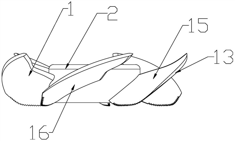
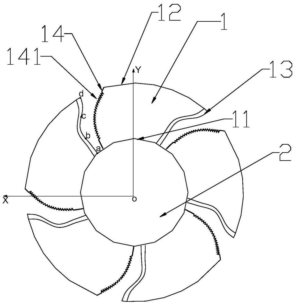
[0045] like figure 1 and 2 As shown, a bionic axial flow wind wheel includes a hub 2 and a blade 1 installed on the circumferential side wall of the hub 2, and the material of the wind rotor blade 1 is one of plastic, metal or a combination of both . The blade 1 includes a blade root 11 and a blade top 12, the blade root 11 is a part in contact with the hub 2, the blade top 12 is opposite to the blade root 11 and away from the blade root 11 Part, the blade 1 also includes a blade leading edge 13 and a blade trailing edge 14 opposite to the blade leading edge 13, along the direction from the blade leading edge 13 to the blade trailing edge 14, the contour line at the blade leading edge 13 Include at least two curves with opposite bending directions. The projection line of the contour line of the leading edge 13 of the blade and the plane perpendicular to the axis of the hub 2 also includes at least two curves with opposite bending directions.
[0046] The blade leading edge...
Embodiment 2
[0056] like Figure 8 As shown, this embodiment only describes the differences from the above embodiments. In this embodiment, the contour line of the leading edge 13 of the blade includes the first contour line ab close to the blade root 11, and the first contour line ab away from the blade root 11. 11 and the second contour line bc connected with the first contour line ab, the first contour line ab and the second contour line bc are curves with opposite bending directions, and the center of curvature of the first contour line ab Located on the outer side of the blade leading edge 13 and set away from the blade leading edge 13, so that the first contour line ab bends toward the blade trailing edge 14 and inwardly of the blade; the curvature of the second contour line bc The center is located on the inner side of said blade leading edge 13 and close to said blade leading edge 13 so that the second contour line bc is curved towards the blade leading edge 13 towards the blade ex...
Embodiment 3
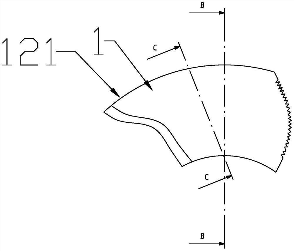
[0058] This embodiment only describes the differences from the above embodiments. In this embodiment, the blade tip 12 is provided with multi-layer deflecting parts 121. The number of the deflecting parts 121 is at least two layers. The deflection parts 121 are sequentially arranged at intervals from the blade trailing edge 14 to the blade leading edge 13 , and multiple layers of the deflection parts 121 make there be several gaps on the blade tip 12 along the blade leading edge 13 to the blade trailing edge 14 . That is, there is a gap between every two layers of deflecting parts 121 . This design structure is similar to the multi-layer feather structure at the top of a bird's feather, and the multi-layer deflecting parts 121 are deflected toward the suction surface at the same time.
PUM
 Abstract
Description
Claims
Application Information
 - R&D
- Intellectual Property
- Life Sciences
- Materials
- Tech Scout
- Unparalleled Data Quality
- Higher Quality Content
- 60% Fewer Hallucinations
Browse by: Latest US Patents, China's latest patents, Technical Efficacy Thesaurus, Application Domain, Technology Topic, Popular Technical Reports.
© 2025 PatSnap. All rights reserved.Legal|Privacy policy|Modern Slavery Act Transparency Statement|Sitemap|About US| Contact US: help@patsnap.com