A Force-Compensated Pressure Differential Oil Return Valve and Design Method of Force-Compensated Parameters

A technology of oil return valve and compensation parameters, which is applied in the design field of force-compensated differential pressure oil return valve and force compensation parameters, can solve the problems of system flow characteristic changes, pressure difference deviation from the expected value, and adverse effects of the whole machine control, etc. Achieve the effects of stable flow characteristics, improved control accuracy, and strong practicability

Active Publication Date: 2021-10-22
AECC SHENYANG ENGINE RES INST
View PDF8 Cites 0 Cited by
  • Summary
  • Abstract
  • Description
  • Claims
  • Application Information

AI Technical Summary

Problems solved by technology

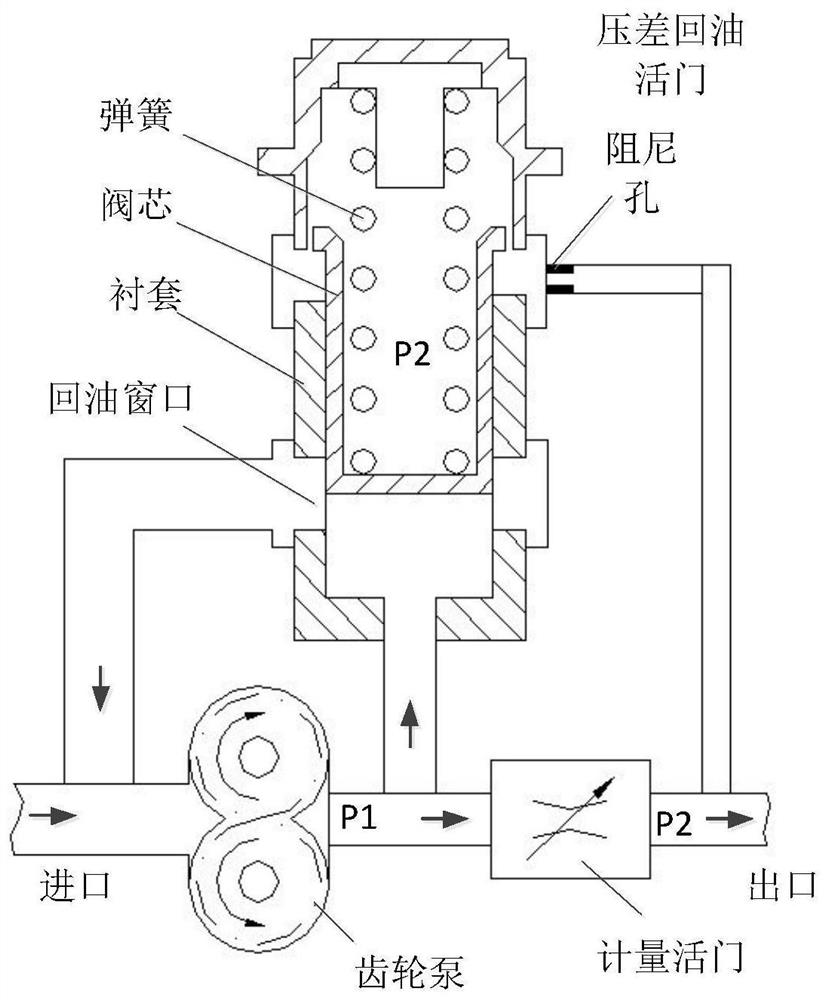
[0021] Both the spring force increment and the steady-state hydraulic force are proportional to the opening of the oil return window, so for figure 1 For the system shown, the smaller the opening of the metering valve, the larger the oil return volume, the larger the opening of the oil return window, and the more the pressure difference deviates from the desired value. Negative Effects

Method used


Image

  • A Force-Compensated Pressure Differential Oil Return Valve and Design Method of Force-Compensated Parameters
  • A Force-Compensated Pressure Differential Oil Return Valve and Design Method of Force-Compensated Parameters
  • A Force-Compensated Pressure Differential Oil Return Valve and Design Method of Force-Compensated Parameters

Examples


Embodiment Construction

[0060] In order to make the purpose, technical solution and advantages of the application more clear, the technical solution in the embodiment of the application will be described in more detail below in conjunction with the drawings in the embodiment of the application. In the drawings, the same or similar reference numerals denote the same or similar elements or elements having the same or similar functions throughout. The described embodiments are some, but not all, embodiments of the application. The embodiments described below by referring to the figures are exemplary, and are intended to explain the present application, and should not be construed as limiting the present application. Based on the embodiments in this application, all other embodiments obtained by persons of ordinary skill in the art without creative efforts fall within the protection scope of this application. Embodiments of the present application will be described in detail below in conjunction with th...


PUM


Abstract

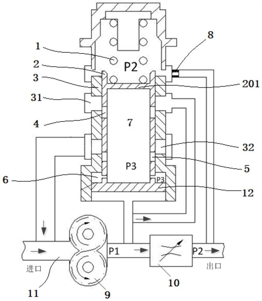
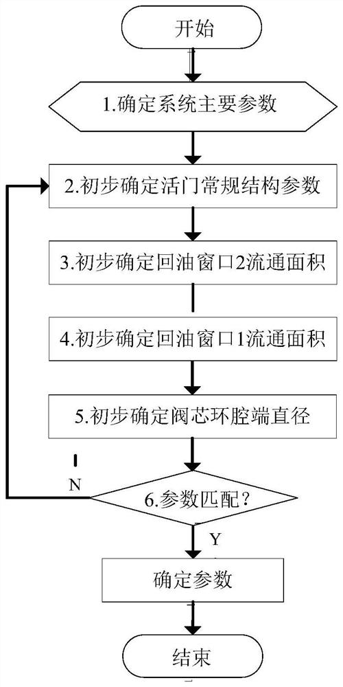
This application belongs to the technical field of constant pressure difference flow control, and particularly relates to a force compensation type pressure difference oil return valve and a force compensation parameter design method; it relates to a force compensation type pressure difference oil return valve, including a bushing, a valve core, a spring, and a gear Pump, metering valve and damping hole; a baffle is set in the inner cavity of the valve core to form a central cavity, the first and second oil return windows are opened on the wall of the valve core, and the matching first 1. The second oil return chamber; the open end of the bottom of the bushing is connected to the fuel oil inlet and outlet pipeline, and a piston is arranged in the inner chamber, and the upper part of the piston forms a ring chamber that communicates with the central chamber. The force-compensated differential pressure oil return valve of this application eliminates the influence of the spring force increment and steady-state hydraulic force on the differential pressure, keeps the pressure differential of the oil return valve at a relatively stable position, and the flow characteristics of the entire system are more stable , which improves the control precision of the control system; moreover, the design method of force compensation parameters can be applied in engineering and has strong practicability.

Description

technical field [0001] The application belongs to the technical field of constant pressure difference flow control, and in particular relates to a force compensation type pressure difference oil return valve and a force compensation parameter design method. Background technique [0002] Aeroengine and gas turbine fuel control systems widely adopt the principle of constant pressure difference flow control, that is, the pressure difference between the front and rear of the metering valve is kept constant through the pressure difference maintaining unit (the following "pressure difference" refers to the pressure difference before and after the metering valve), so that the fuel flow is only equal to The flow area is related. On this premise, the metering valve is controlled to change the fuel flow area to adjust the fuel flow. [0003] In different types of fuel control systems, there are various types of differential pressure maintaining units. According to whether there is an ...

Claims


Application Information

Patent Timeline
Patent Type & Authority Patents(China)
IPC IPC(8): F02C7/232F02C9/32G06F30/20G06F113/08G06F119/14
CPCF02C7/232F02C9/263F02C9/32G06F30/20G06F2113/08G06F2119/14
Inventor 左伟崔利丰李宣莹韩崇鹏
Owner AECC SHENYANG ENGINE RES INST
Why Eureka
Try Eureka