Multi-process auxiliary construction equipment for road construction
A kind of construction equipment and road construction technology, applied in the direction of roads, roads, road repairs, etc., can solve problems such as on-site environmental pollution
- Summary
- Abstract
- Description
- Claims
- Application Information
AI Technical Summary
Problems solved by technology
Method used
Image

Examples
specific Embodiment approach 1
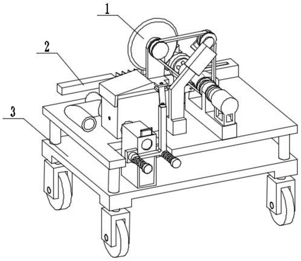
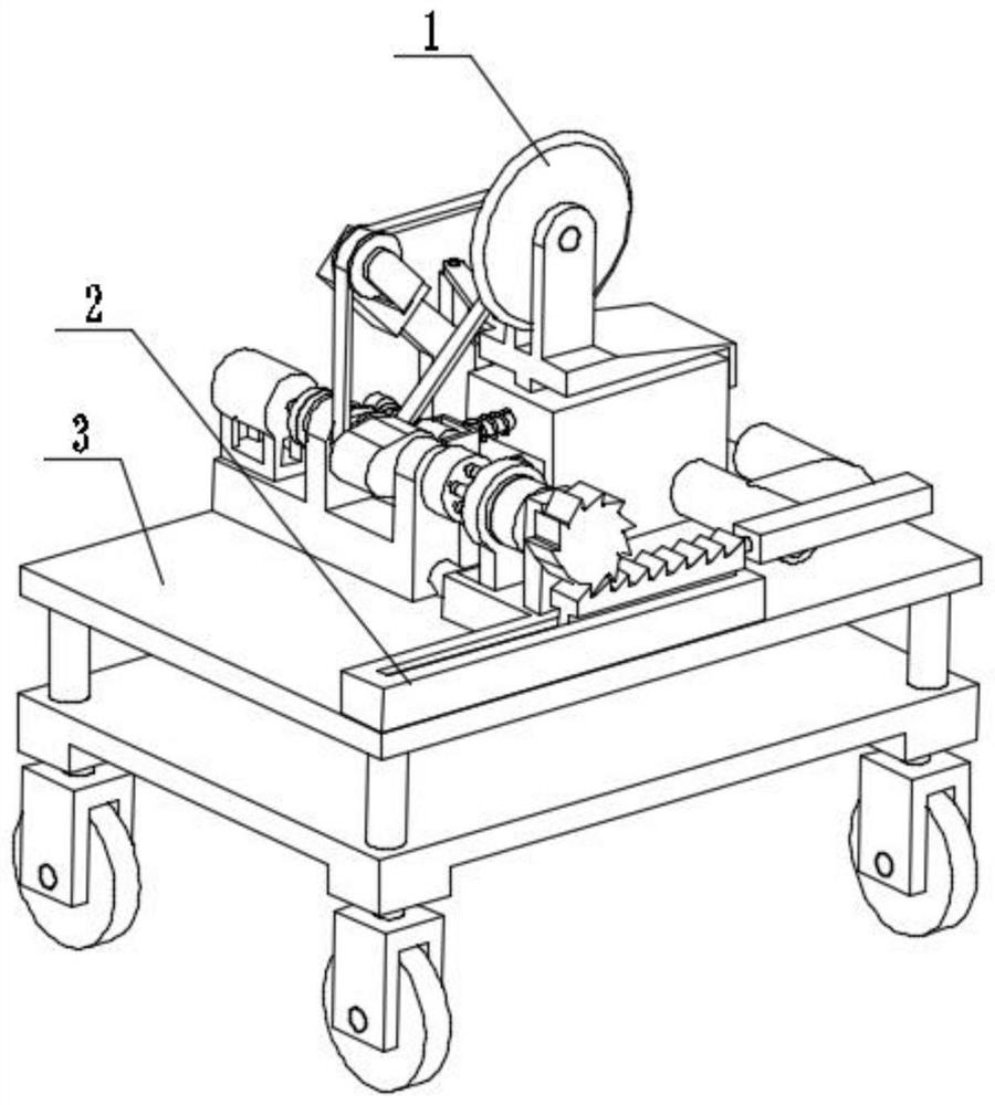
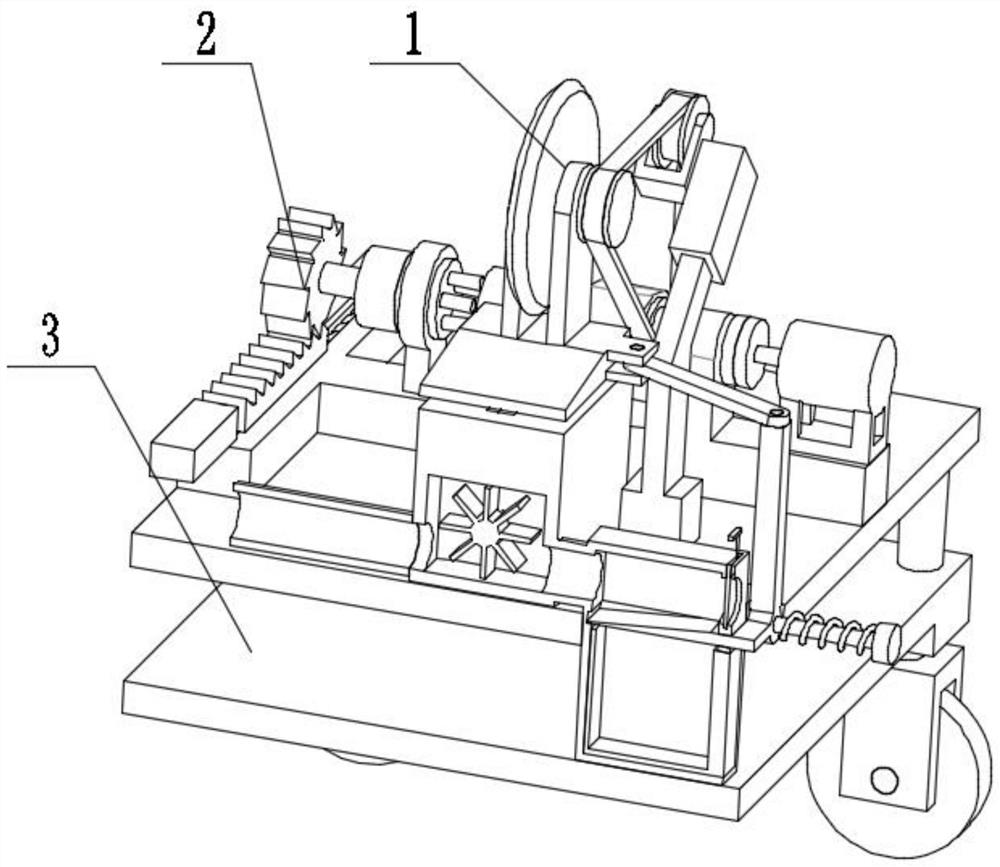
[0030] Combine below figure 1 , figure 2 , image 3 , Figure 4 , Figure 5 , Image 6 , Figure 7 , Figure 8 , Figure 9 , Figure 10 , Figure 11 , Figure 12 , Figure 13 , Figure 14 , Figure 15 Describe this embodiment. The present invention relates to an auxiliary construction equipment, more specifically, a multi-process auxiliary construction equipment for road construction, including a cutting mechanism 1, a grinding mechanism 2, and a frame mechanism 3. The equipment can cut while After the feeding is completed, the equipment can switch to the synchronous grinding mode, the equipment can collect the waste slag generated by cutting and grinding, and the equipment can balance the collection pressure.
[0031] The cutting mechanism 1 is connected with the frame mechanism 3 , and the grinding mechanism 2 is connected with the frame mechanism 3 .
specific Embodiment approach 2
[0033] Combine below figure 1 , figure 2 , image 3 , Figure 4 , Figure 5 , Image 6 , Figure 7 , Figure 8 , Figure 9 , Figure 10 , Figure 11 , Figure 12 , Figure 13 , Figure 14 , Figure 15 Describe this embodiment, this embodiment will further explain the first embodiment, the cutting mechanism 1 includes a collection box 1-1, a seat with an inner cavity 1-2, a motor 1-3, a five-hole wheel 1-4, and a bearing seat 1-5, belt shaft cam 1-6, grooved pulley 1-7, belt 1-8, coupling 1-9, motor A1-10, tensioning sheave 1-11, sheave seat 1-12, Chute 1-13, curved arm support 1-14, shaft cutter 1-15, bearing seat I1-16, inclined plate 1-17, nozzle A1-18, nozzle B1-19, negative pressure pipe 1- 20. Drawer box 1-21, ladder rod 1-22, spring 1-23, special-shaped sliding seat 1-24, opening 1-25, filter plate 1-26, hinged arm 1-27, material retaining inclined plate 1- 28. Slot I1-29, wind wheel with shaft 1-30, coupling A1-31, cavity 1-32, step groove 1-33, step sli...
specific Embodiment approach 3
[0035] Combine below figure 1 , figure 2 , image 3 , Figure 4 , Figure 5 , Image 6 , Figure 7 , Figure 8 , Figure 9 , Figure 10 , Figure 11 , Figure 12 , Figure 13 , Figure 14 , Figure 15 Describe this embodiment, this embodiment will further explain the first embodiment, the grinding mechanism 2 includes a grinding plate 2-1, a sliding ratchet plate 2-2, an incomplete ratchet with a shaft 2-3, and a bearing seat II2-4 , Five-hole wheel A2-5, sliding bearing seat 2-6, transmission wheel 2-7, five-bar drive protrusion 2-8, belt limit slot seat 2-9, hydraulic cylinder support 2-10, hydraulic cylinder 2- 11. Inner limit rod A2-12, return spring 2-13, matching hole A2-14, hydraulic rod 2-15, grinding plate 2-1 connected with sliding ratchet plate 2-2, sliding ratchet plate 2-2 It is meshed with the incomplete ratchet wheel 2-3, the incomplete ratchet wheel 2-3 is rotationally connected with the bearing seat II2-4, the bearing seat II2-4 is connected wit...
PUM
 Abstract
Description
Claims
Application Information
 - R&D
- Intellectual Property
- Life Sciences
- Materials
- Tech Scout
- Unparalleled Data Quality
- Higher Quality Content
- 60% Fewer Hallucinations
Browse by: Latest US Patents, China's latest patents, Technical Efficacy Thesaurus, Application Domain, Technology Topic, Popular Technical Reports.
© 2025 PatSnap. All rights reserved.Legal|Privacy policy|Modern Slavery Act Transparency Statement|Sitemap|About US| Contact US: help@patsnap.com