
Optical wand straightening device

A straightening and light bar technology, applied in glass re-molding, glass manufacturing equipment, glass forming, etc., can solve the problems of poor effect, waste of manpower and material resources, and difficulty in straightening, and achieve straightening. Good effect, saving manpower and material resources

Pending Publication Date: 2021-01-22
久智光电子材料科技有限公司 +1
View PDF3 Cites 1 Cited by
  • Summary
  • Abstract
  • Description
  • Claims
  • Application Information

AI Technical Summary

Problems solved by technology

This method depends entirely on the observation and judgment of human eyes when provoking the softened part to a straight state. There is no objective reference. When encountering continuous small-angle bending, it is not only difficult to straighten the state, but also needs repeated adjustments , a waste of manpower and material resources, the effect is not good

Method used


Image

  • Optical wand straightening device
  • Optical wand straightening device
  • Optical wand straightening device

Examples


Embodiment Construction

[0020] In order to enable those skilled in the art to better understand the technical solution of the application, the application will be described in detail below in conjunction with the accompanying drawings. The description in this part is only exemplary and explanatory, and should not have any limiting effect on the protection scope of the application. .

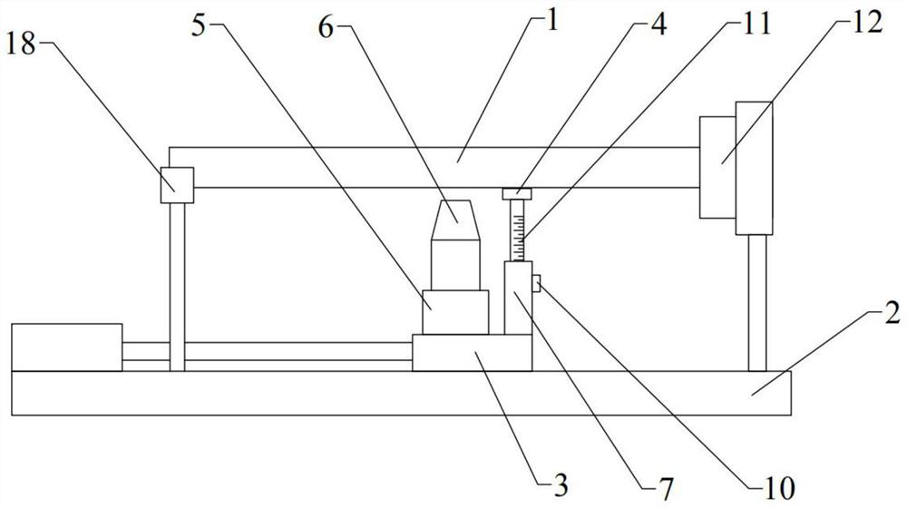
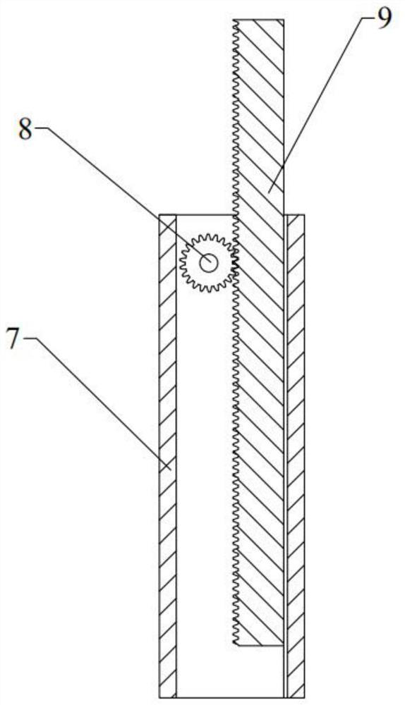
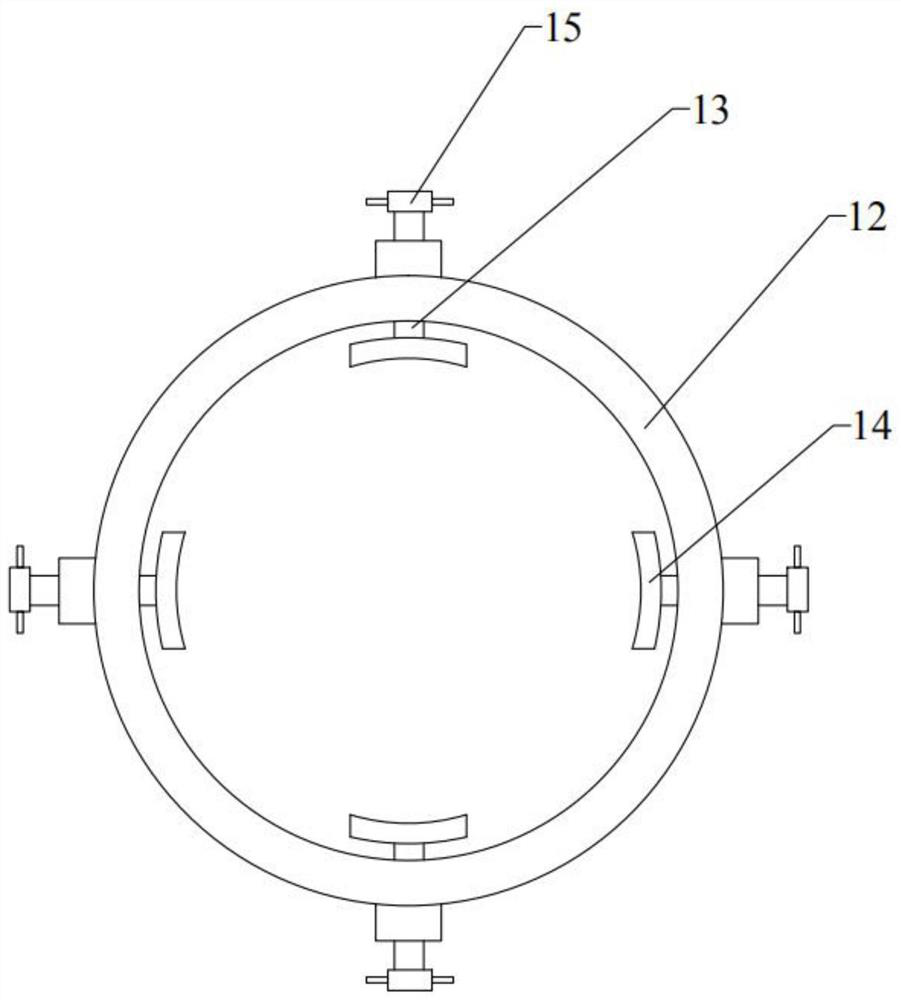
[0021] Please refer to figure 1 , the present embodiment provides a light rod straightening device, including a base 2; above one end of the base 2, a clamping mechanism for clamping one end of the light rod 1 and a device for driving the clamping mechanism to rotate Rotary drive, the rotary drive can be a servo motor (not shown); the base 2 is also slidably provided with a straightening platform 3; one end of the straightening platform 3 is connected with a linear drive; the linear drive The device can be a hydraulic cylinder or an electric push rod; the straightening platform 3 is located below the light rod 1, and i...


PUM


Abstract

The invention provides an optical wand straightening device. The optical wand straightening device comprises a base; a clamping mechanism used for clamping one end of an optical wand and a rotation driving device used for driving the clamping mechanism to rotate are arranged above one end of the base; a straightening platform is further arranged on the base in a sliding mode; one end of the straightening platform is connected with a linear driving device; the straightening platform is positioned below the optical wand, and the sliding direction of the straightening platform is parallel to thelength direction of the optical wand; a straightening plate is installed at the end, close to the clamping mechanism, of the straightening platform through a height adjusting mechanism, and a flame spray gun is installed at the end, away from the clamping mechanism, of the straightening platform through a gun rack. The optical wand is driven to rotate through the clamping mechanism and the rotarydriving device, the straightening platform is driven to slide through the linear driving device, the flame spray gun located on the straightening platform heats and softens the light bar firstly, andthen the softened optical wand is straightened and shaped through the straightening plate; the straightening platform slides from one end of the optical wand to the other end of the optical wand to complete straightening of the optical wand, repeated adjustment is not needed, manpower and material resources are saved, and the straightening effect is good.

Description

technical field [0001] The present application relates to the technical field of optical rod shaping, in particular to an optical rod straightening device. Background technique [0002] With the development of science and technology, the application fields of quartz glass products are becoming wider and wider, and the requirements for the straightness of quartz materials are also getting higher and higher. But before the light rod is placed on the lathe, it is not completely straight, but slightly bent, or even bent successively. The traditional method of straightening the light rod is: fix one end of the light rod on the lathe, heat the light rod from the fixed end until it softens, and judge with human eyes whether the light rod in the heated and softened part is bent, and if there is a bend, use a graphite rod Lift the curved part until it is straight, and repeat to the other end of the light stick. This method depends entirely on the observation and judgment of human e...

Claims


Application Information

Patent Timeline
Patent Type & Authority Applications(China)
IPC IPC(8): C03B23/045C03B23/043
CPCC03B23/045C03B23/043
Inventor 张超李建坤郝志广郭磊薛艳高
Owner 久智光电子材料科技有限公司
Learn More