
Lifting and horizontal conveying table

A technology for leveling and transporting boards, applied in the direction of lifting frames, lifting devices, etc., can solve the problems of poor stability of ladders, failure to meet the requirements of transportation, and potential safety hazards, so as to reduce labor intensity, improve labor efficiency, and have a wide range of applications Effect

Pending Publication Date: 2021-01-22
UNIV OF SCI & TECH LIAONING
View PDF0 Cites 6 Cited by
  • Summary
  • Abstract
  • Description
  • Claims
  • Application Information

AI Technical Summary

Problems solved by technology

[0004] Similarly, in other production and construction processes, ladders are often needed for heights and positions that workers cannot reach when standing naturally. Ladders are not only less stable, but also pose potential safety hazards, and cannot provide workers with a larger working space. There are also security risks
For the occasion where the position of the construction site changes in the horizontal or vertical direction, when using a ladder, you can only repeat the process of climbing up and down and carrying the ladder, which is time-consuming and labor-intensive, and the efficiency is low
[0005] Existing lifting devices often use hydraulic lifting methods, such as hydraulic scissor lifts, but it is difficult and costly to realize synchronous control of multiple hydraulic cylinders, and there is a risk of oil leakage
The safety factor of the pulley lift is low, and it only has a single lifting function, which cannot meet the requirements of different heights and different horizontal positions.

Method used


Image

  • Lifting and horizontal conveying table
  • Lifting and horizontal conveying table
  • Lifting and horizontal conveying table

Examples


Embodiment Construction

[0027] The specific embodiment of the present invention will be further described below in conjunction with accompanying drawing:

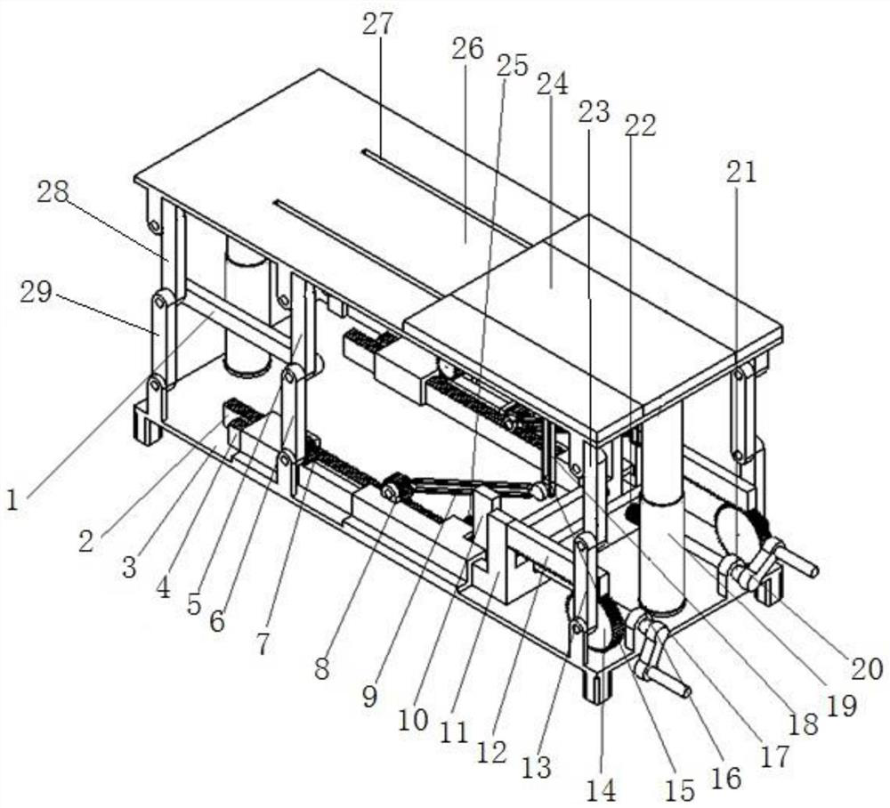
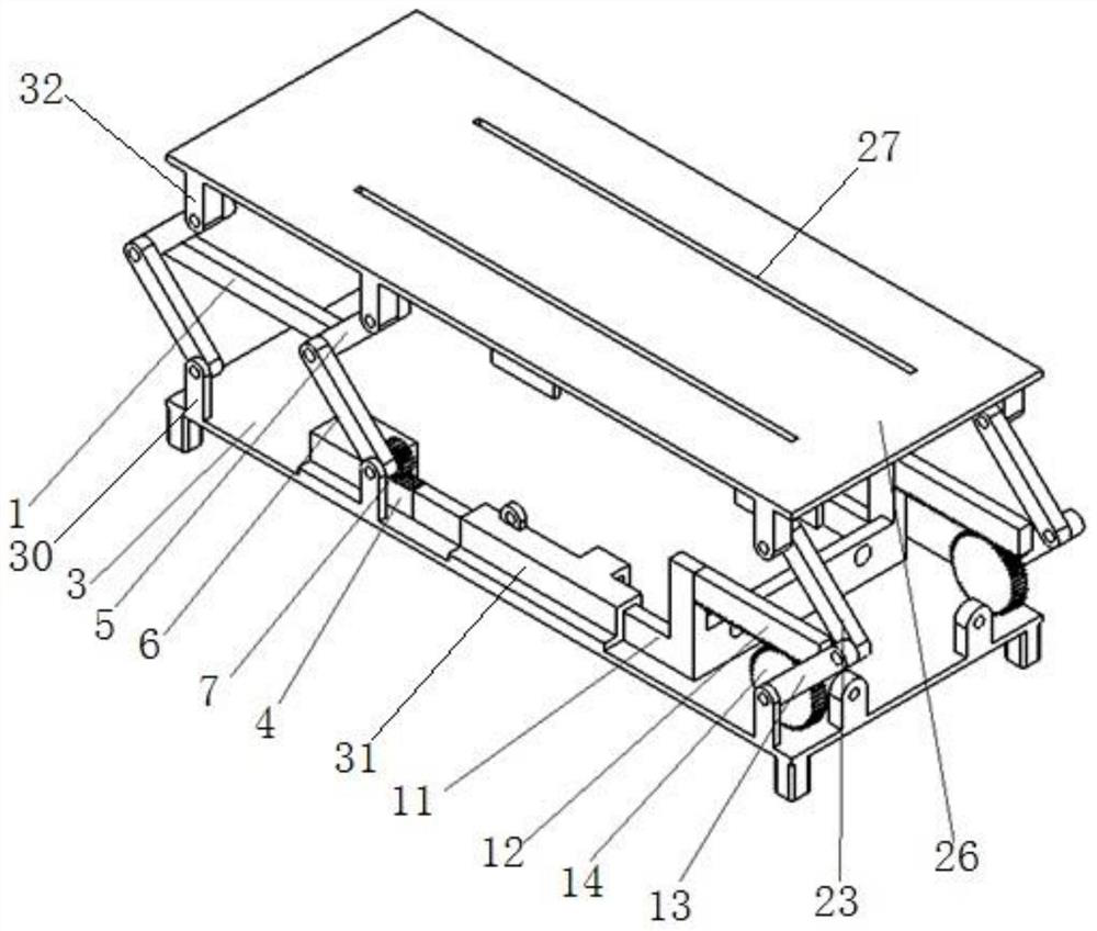
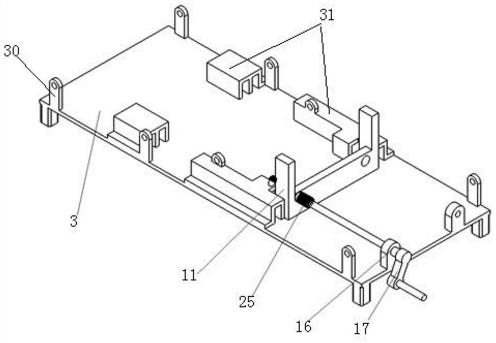
[0028] Such as Figure 1-Figure 5 As shown, a kind of lifting and horizontal conveying platform of the present invention comprises base 3, carrying platform 26, conveying plate 24, lifting mechanism and conveying plate translation mechanism; Lead screw one 22, at least 2 groups of transmission mechanism one and telescoping rod 19 constitute, transmission mechanism one is made up of rack one, gear one, active fork and driven fork; Described sliding seat one 11 is located on the base 3, Rocker 120 drives sliding seat 11 to slide through lead screw 122, rack 1 on sliding seat 11 meshes with gear 1 for transmission; gear 1 is fixedly connected to the bottom of the active swing rod; one end of the active swing rod is hinged to base 3 , the other end of the active swing link is hinged with one end of the driven swing link, and the other end of the driv...


PUM


Abstract

The invention relates to a lifting and horizontal conveying table. The lifting and horizontal conveying table comprises a base, a bearing table, a conveying plate, a lifting mechanism and a conveyingplate translation mechanism, wherein the lifting mechanism comprises a slide base 1, a rocking handle 1, a lead screw 1, at least two sets of transmission mechanisms 1 and an extension rod; the transmission mechanisms 1 comprise racks 1, gears 1, driving swing rods and driven swing rods; when the rocking handle 1 rotates, the gears 1 drive the driving swing rods and the driven swing rods to rotatearound respective hinge points, and the bearing table vertically lifts and moves under the limiting effect of the extension rod; the conveying plate is arranged at the top of the bearing table; the conveying plate translation mechanism consists of a slide base 2, a rocking handle 2, a lead screw 2 and at least one set of transmission mechanisms 2; and when the rocking handle 2 rotates, the swingrods are driven to swing through gears 2, and a slide block and a slide rod are matched to drive the conveying plate to horizontally slide on the bearing table. The lifting and horizontal conveying table achieves the lifting and translation functions, is simple in structure, convenient to adjust, low in manufacturing cost and wide in application range, can effectively improve the labor efficiency,and reduces the labor intensity.

Description

technical field [0001] The invention relates to an object carrier, in particular to an elevating and horizontal conveying platform. Background technique [0002] Among the many express sorting points, handling express delivery is the most basic work item that is carried out every day. For many express sorting points, trucks will deliver a load of goods all the time, and then carry out manual handling, especially when some shopping festivals come, there will be a lot of express delivery. At present, express delivery usually uses manual handling, but when there are too many goods, the efficiency of manual handling obviously cannot meet the requirements. [0003] Using special equipment to reduce work intensity and improve labor efficiency is a common method, such as using conveyor belts, but conventional conveyor belts are generally fixed and large in size, which is inconvenient to use. In addition, the height of the conveyor belt is also fixed, and the height of the conveyo...

Claims


Application Information

Patent Timeline
IPC IPC(8): B66F7/06B66F7/28
CPCB66F7/06B66F7/0633B66F7/28
Inventor 马学东陈健张凡陈晨杜昱霖周大鹏
Owner UNIV OF SCI & TECH LIAONING
Learn More