A special fixture and method for machining the tenon end face of aero-engine blade

An aero-engine and end face processing technology, which is applied in the direction of manufacturing tools, metal processing equipment, metal processing machinery parts, etc., can solve the problems of uneven transmission of clamping force and deformation of blade clamping, and achieve simple structure, convenient installation and positioning accurate effect

Active Publication Date: 2022-04-12
西安三航动力科技有限公司
View PDF14 Cites 3 Cited by
  • Summary
  • Abstract
  • Description
  • Claims
  • Application Information

AI Technical Summary

Problems solved by technology

However, the fixture adopts a hard clamping method, and the clamping force cannot be evenly transmitted to the profile of the blade body, which may cause deformation of the blade during clamping

Method used


Image

  • A special fixture and method for machining the tenon end face of aero-engine blade
  • A special fixture and method for machining the tenon end face of aero-engine blade
  • A special fixture and method for machining the tenon end face of aero-engine blade

Examples


Embodiment Construction

[0031] The embodiments described below by referring to the figures are exemplary and are intended to explain the present invention and should not be construed as limiting the present invention.

[0032] In describing the present invention, it should be understood that the terms "center", "longitudinal", "transverse", "length", "width", "thickness", "upper", "lower", "front", " Orientation indicated by rear, left, right, vertical, horizontal, top, bottom, inside, outside, clockwise, counterclockwise, etc. The positional relationship is based on the orientation or positional relationship shown in the drawings, which is only for the convenience of describing the present invention and simplifying the description, rather than indicating or implying that the referred device or element must have a specific orientation, be constructed and operated in a specific orientation, Therefore, it should not be construed as limiting the invention.

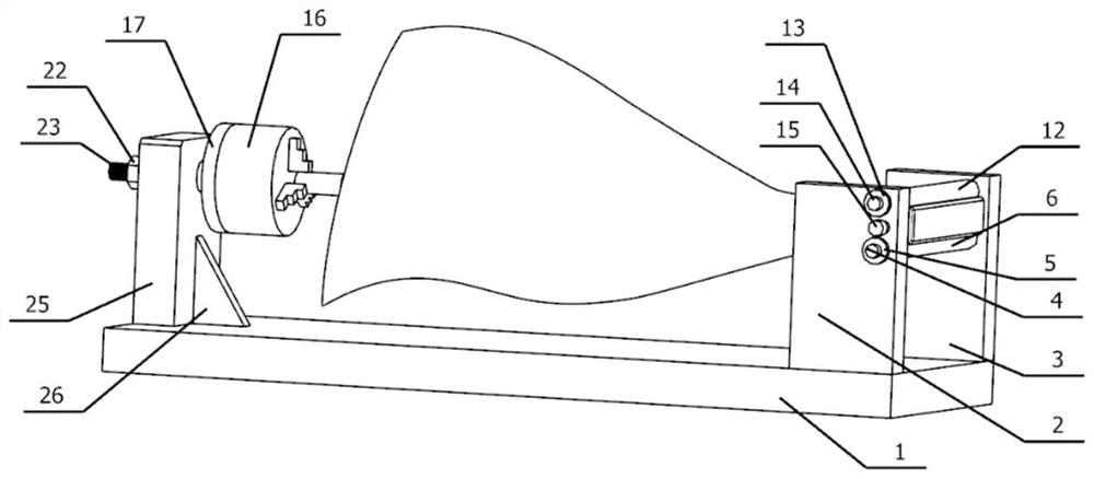
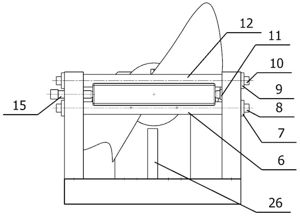
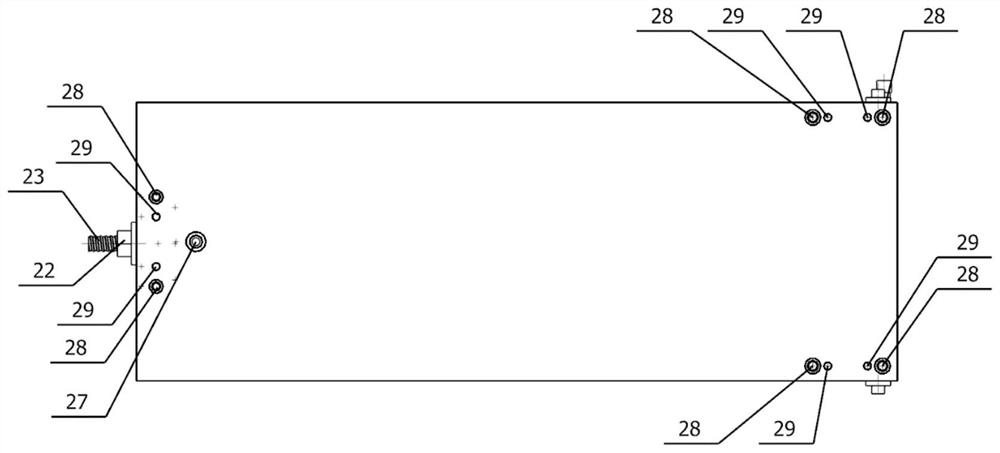
[0033] This embodiment is a special fixture ...


PUM


Abstract

The invention discloses a special fixture and method for processing the tenon root end face of an aero-engine blade, belonging to the technical field of numerical control machining of aero-engine blades; comprising a base, a blade tip clamping assembly, a blade tenon root wedge-shaped surface clamping assembly, and a blade tenon root side clamp Clamping assembly; the blade tenon root wedge surface clamping assembly clamps the blade tenon root wedge surface through the first cylindrical positioning shaft and the second cylindrical positioning shaft; the blade tenon root side clamping assembly includes a ball head positioning pin and a ball head thread clamping and positioning The pin is clamped and positioned from the side of the tenon root of the blade; the blade tip clamping assembly includes the front plate of the base, the three-jaw chuck and the chuck base; the three-jaw chuck is installed on the side wall of the front plate of the base through the chuck base Above: The pulling force of the blade tip is positioned by the three-jaw chuck, and the axial displacement of the blade along its process cylinder axis is limited. The invention realizes the positioning and clamping of the entire engine blade under the condition of ensuring that the engine blade is not damaged during the blade clamping process.

Description

technical field [0001] The invention belongs to the technical field of numerical control machining of aeroengine blades, and in particular relates to a special fixture and method for machining the tenon root end surface of aeroengine blades. Background technique [0002] The blade is a key component of the aero-engine and plays an important role in the engine. The processing quality of the blade seriously affects the overall performance of the aero-engine. The blades mainly have the following characteristics: the blades are thin-walled parts with complex curved surfaces and large torsion angles; the blade materials are mainly difficult-to-machine materials such as titanium alloys, and require high geometric precision. As a high-efficiency and low-cost process, forging has been widely used in the field of aero-engine blade blank manufacturing. Limited by the current forging technology, the mortise of the blade cannot be precision forged and needs to be processed by CNC. The...

Claims


Application Information

Patent Timeline
Patent Type & Authority Patents(China)
IPC IPC(8): B23Q3/06B23B31/10
CPCB23Q3/06B23Q3/062B23Q3/063B23B31/10
Inventor 温长喜乔敏彭鹏吕霄唐天丞
Owner 西安三航动力科技有限公司
Why Eureka
Try Eureka