
Numerical control laser cutting and automatic discharging device

A CNC laser and automatic cutting technology, applied in laser welding equipment, welding equipment, metal processing equipment and other directions, can solve the problems of increasing the manual operation items of the staff and the trouble of operation, so as to reduce the manual operation items and make the operation simple and fast. Effect

Inactive Publication Date: 2021-01-22
杨宝辉
View PDF1 Cites 4 Cited by
  • Summary
  • Abstract
  • Description
  • Claims
  • Application Information

AI Technical Summary

Problems solved by technology

[0003] In the field of prior art, laser cutting mostly adopts similar application publication number: CN105414773A The invention relates to the field of machinery and laser equipment, especially for auto parts, hardware tools, medical equipment, instruments and meters, optical communication devices, gold and silver jewelry, A laser cutting machine for many industries such as craft gifts, packaging and printing, mechanical equipment, etc., including a machine tool body, characterized in that: the machine tool body is provided with a lifting mechanism, and a workbench assembly is arranged above the lifting mechanism. The workbench assembly described above includes a workbench and a workbench needle plate arranged on the workbench, the side of the workbench in the Y-axis direction is provided with a sheet material clamping mechanism, and the workbench needle plate is provided with several A sheet metal universal translation support mechanism parallel to the side of the workbench in the X-axis direction. A beam is provided above the side of the workbench in the X-axis direction. The overall waste sheet enclosed on the outside of the needle plate of the workbench, the overall waste sheet on the surface of the workbench after laser cutting needs to be manually unloaded by the staff for processing, the operation is more troublesome, and the finished products and cutting debris after cutting will be mixed Together, the staff needs to manually sort the operation, and the staff manual operation item is added

Method used


Image

  • Numerical control laser cutting and automatic discharging device
  • Numerical control laser cutting and automatic discharging device
  • Numerical control laser cutting and automatic discharging device

Examples


Embodiment Construction

[0024] The following will clearly and completely describe the technical solutions in the embodiments of the present invention with reference to the accompanying drawings in the embodiments of the present invention. Obviously, the described embodiments are only some, not all, embodiments of the present invention. Based on the embodiments of the present invention, all other embodiments obtained by persons of ordinary skill in the art without making creative efforts belong to the protection scope of the present invention.

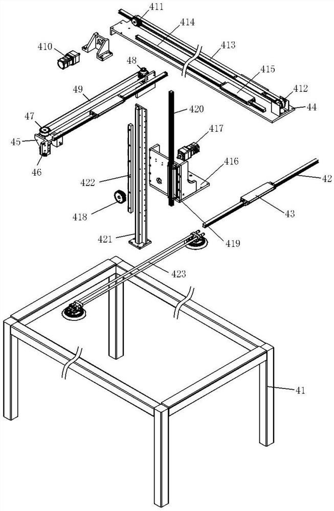
[0025] see Figure 1-3 , the present invention provides a technical solution: a CNC laser cutting automatic blanking device, comprising: a base 1, a CNC laser cutting device 2, a discharge mechanism 3, a plate waste blanking mechanism 4, a control box 5 and a loading and unloading area 6 ; The CNC laser cutting device 2 is arranged on the top left side of the base 1 through the bracket along the left and right directions. The box 5 is controlled to carry out ...


PUM


Abstract

The invention discloses a numerical control laser cutting and automatic discharging device. The device comprises a base, a numerical control laser cutting device, a material discharge mechanism, a plate waste discharging mechanism, a control box and a loading and unloading area. The numerical control laser cutting device is arranged on the left side of the top end of the base through a support inthe left-right direction. The material discharge mechanism is arranged at the lower end of the numerical control laser cutting device in the left-right direction. The plate waste discharging mechanismis arranged on the right side of the top end of the base in the left-right direction and located on the outer side of the numerical control laser cutting device. The control box is installed on the front side of the top end of the base through a support. According to the numerical control laser cutting and automatic discharging device, automatic unloading of whole waste plates after laser cuttingcan be achieved, manual operation of workers is not needed, operation is easier and faster, automatic screening of cut machined finished products and cutting chippings is achieved, manual sorting ofthe workers is not needed, manual operation items of the workers are reduced, and time and labor are saved.

Description

technical field [0001] The invention relates to the technical field of laser cutting, in particular to a numerical control laser cutting automatic unloading device. Background technique [0002] Laser cutting uses a high-energy-density laser beam to heat the workpiece, causing the temperature to rise rapidly and reach the boiling point of the material in a very short period of time. The material begins to vaporize and form steam. The steam is ejected at a high speed. , form an incision on the material, use laser cutting equipment to cut stainless steel below 4mm, and add oxygen to the laser beam to cut 20mm thick carbon steel, but after adding oxygen to cut, a thin oxide film will be formed on the cutting surface. The maximum thickness can be increased to 20mm, but the size error of the cutting parts is large, and the price of laser cutting equipment is quite expensive. However, due to the reduced cost of subsequent processing, it is still feasible to use this equipment in m...

Claims


Application Information

Patent Timeline
IPC IPC(8): B23K26/38B23K26/70
CPCB23K26/38B23K26/702
Inventor 不公告发明人
Owner 杨宝辉
Learn More