


Quick Research
Generate reliable direction feasibility study reports for your R&D in just a few steps.

Technical Q&A
Discover and master advanced knowledge NOW. Basics, ideas, possibilities, all at once.

Find Solutions
As an expert in R&D theories, this can generate solutions to your technical problems instantly.

Evaluate Feasibility
Analyze your overall solution with one click, know your potential R&D risks in advance.

Monitor Landscape
Get weekly tech updates, stay abreast of the latest tech innovations and key insights.
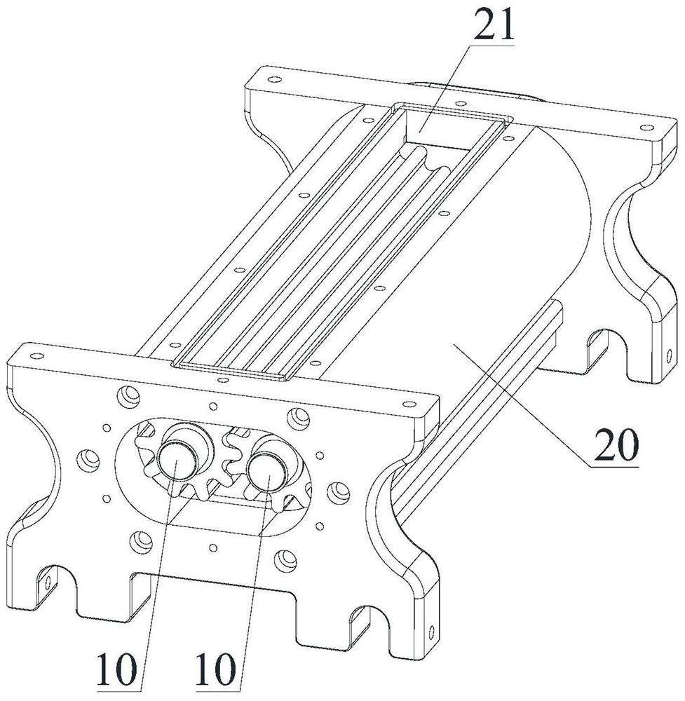
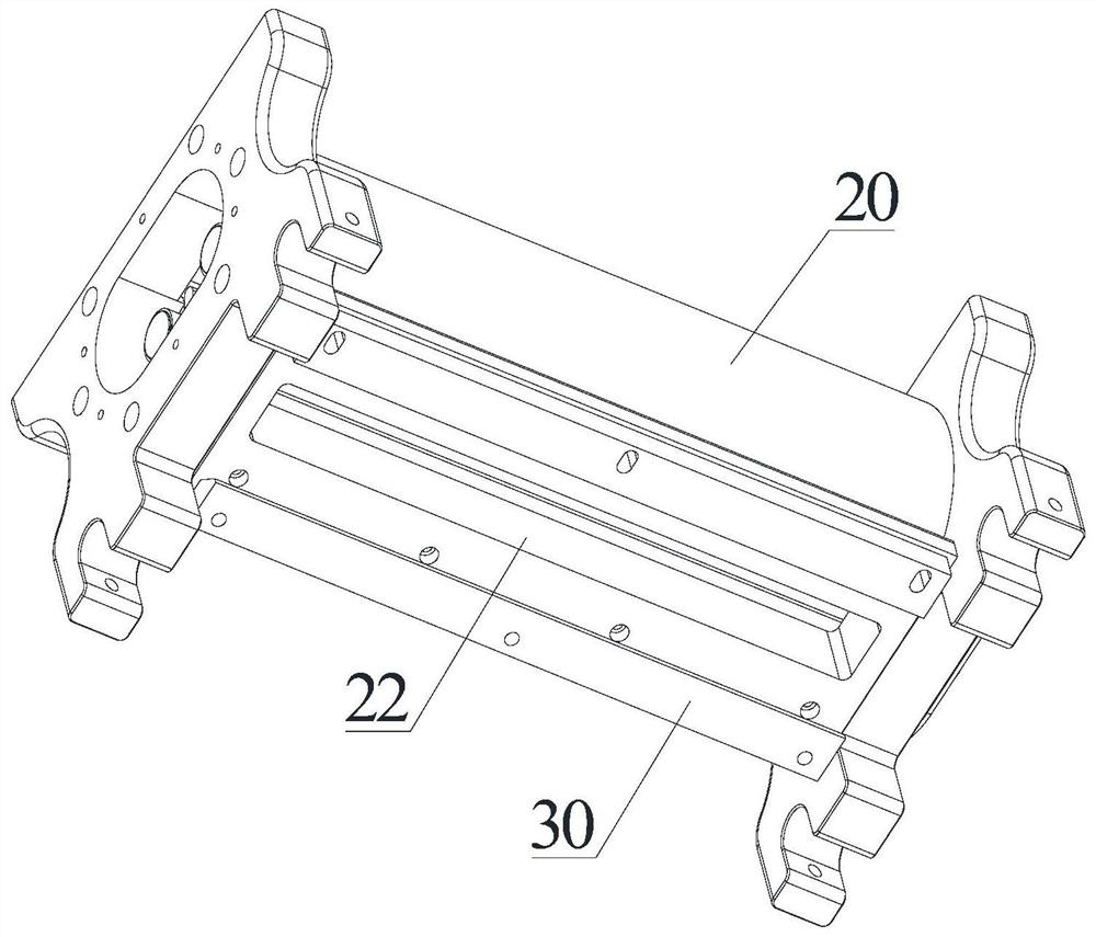
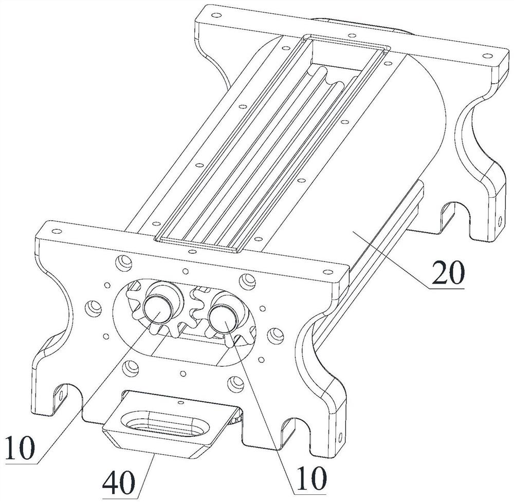
Slurry discharging mechanism for food processing and slurry injection machine thereof
A food processing and slurry technology, applied in bakery food processing, application, food science and other directions, can solve the problem of inability to accurately control the amount of particulate matter in the slurry, and achieve the goal of ensuring food yield, improving control accuracy and maintaining consistent taste. Effect
- Summary
- Abstract
- Description
- Claims
- Application Information
AI Technical Summary
Problems solved by technology
Method used
Image

Examples
Embodiment 1
[0039] Embodiment one: refer to Figure 5 , The feed teeth 11 are straight teeth, and the two lower feed gear rollers 10 mesh with each other through the straight teeth. The straight tooth shape is the most common form, which has the advantages of simple processing and low manufacturing cost.
Embodiment 2
[0040] Embodiment two: refer to Figure 6-Figure 8 , the shape of the material tooth 11 is C-shaped, which is smooth arc-shaped. The arc angle between the C-shaped teeth is used to accommodate the solid particles that sink in the slurry. The side of the C-shaped tooth is sunken toward the meshing side. The unloading gear rollers 10 are tightly meshed with each other through C-shaped teeth.
Embodiment 3
[0041] Embodiment three: refer to Figure 9-Figure 11 , the shape of the material teeth 11 is V-shaped, and the angle formed by the V-shaped teeth is used to accommodate the solid particles sinking in the slurry. The V-shaped teeth are tightly meshed with each other.
[0042] Material tooth 11 can also be made into other curved tooth shapes except C type or V type.
[0043] Because the slurry contains solid particles, the density of the solid particles is greater than the density of the slurry, so the solid particles will tend to sink. Since the material tooth 11 is made into a C-shaped or V-shaped curved tooth, the concave part with opposite angles is more It is easy to accommodate more solid particles. During the rotation of the feed tooth 11, most of the solid particles will sink and hide in the opposite corner, which is not easy to scatter, and the slurry can easily cross the top surface of the feed tooth 11, because only A small amount of solid particles will move betwe...
PUM
 Abstract
Description
Claims
Application Information
 - R&D Engineer
- R&D Manager
- IP Professional
- Industry Leading Data Capabilities
- Powerful AI technology
- Patent DNA Extraction
Browse by: Latest US Patents, China's latest patents, Technical Efficacy Thesaurus, Application Domain, Technology Topic, Popular Technical Reports.
© 2024 PatSnap. All rights reserved.Legal|Privacy policy|Modern Slavery Act Transparency Statement|Sitemap|About US| Contact US: help@patsnap.com