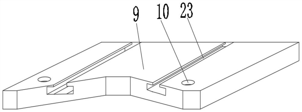
A CNC hydraulic automatic cold welding machine

A technology of cold welding machine and hydraulic press, which is applied in cold pressing connection, mechanical equipment, other manufacturing equipment/tools, etc., can solve the problems of wear and deformation of cold pressing die sockets, threaten the personal safety of staff, reduce work efficiency, etc. The effect of reducing the complexity of use, ensuring personal safety and improving efficiency

Active Publication Date: 2022-01-25
杭州企诚净化科技有限公司
View PDF6 Cites 0 Cited by
  • Summary
  • Abstract
  • Description
  • Claims
  • Application Information

AI Technical Summary

Problems solved by technology

[0004] 1. When the hydraulic automatic cold welding machine is in use, the staff needs to hold the welding parts and insert them into the cold welding mold in the cold welding machine. Generally, the socket on the hydraulic module is small, and the socket in the artificial alignment cold welding mold During the process, it is easy to cause the front end of the weldment to collide with the cold-pressing module, causing the socket on the cold-pressing mold to wear and deform. After each use, the cold-pressing mold needs to be overhauled, which increases the workload of the staff and reduces the work efficiency, and will cause scratches on the surface of the welded parts inserted later, and the position of the welded parts is not fixed, which will lead to confusion on the production site, which is not conducive to the work of the staff;
[0005] 2. After the welding of the welded parts is completed, metal bumps will be formed on the surface of the welding place, which needs to be cut by the staff, and then polished after cutting, and the hydraulic cold welding machine does not have a device for storing the cut metal bumps , there will be a phenomenon of littering, resulting in confusion at the work site, and the surface of the metal bumps is uneven, with many sharp points. If the staff touches the metal bumps, the sharp points on the surface of the metal bumps will hurt the work. personnel, threatening the personal safety of staff

Method used


Image

  • A CNC hydraulic automatic cold welding machine
  • A CNC hydraulic automatic cold welding machine
  • A CNC hydraulic automatic cold welding machine

Examples


Embodiment Construction

[0033]The following will clearly and completely describe the technical solutions in the embodiments of the present invention with reference to the accompanying drawings in the embodiments of the present invention. Obviously, the described embodiments are only some, not all, embodiments of the present invention. Based on the embodiments of the present invention, all other embodiments obtained by persons of ordinary skill in the art without making creative efforts belong to the protection scope of the present invention.

[0034] see Figure 1 to Figure 8 , the present invention provides a technical solution:

[0035] A CNC hydraulic automatic cold welding machine, comprising an upper body 1 and a base 8, the base 8 is fixedly connected to the upper outer surface of the main body 1, and rectangular grooves 2 are opened on both sides of the upper outer surface of the main body 1 The inner surface of the lower end of the rectangular groove 2 is fixedly connected with the first hyd...


PUM


Abstract

The invention discloses a digitally controlled hydraulic automatic cold welding machine, which comprises an upper body and a base, the base is fixedly connected to the upper surface of the main body, and rectangular grooves are opened on both sides of the upper outer surface of the main body. The inner surface of the lower end of the rectangular groove is fixedly connected with a hydraulic press, the outer surface of the upper end of the hydraulic press is fixedly connected with a limiting device, the front and rear edges of the upper outer surface of the main body are fixedly equipped with baffle plates, and the outer surface of the upper end of the base A protective plate is movably connected, and a storage device is slidably connected above the protective plate. Grooves are provided at the joints between the outer surfaces of both sides of the base and the limiting device. The invention can quickly enable the staff to insert the welding parts into the cold-pressing mold, avoiding the collision between the welding parts and the cold-pressing mold when the welding parts are inserted, causing damage to the socket on the cold-pressing mold and making it inconvenient for the welding parts to be inserted later Delay time reduces work efficiency.

Description

technical field [0001] The invention relates to the technical field of hydraulic cold welding, in particular to a numerically controlled hydraulic automatic cold welding machine. Background technique [0002] Cold pressure welding refers to the method of plastically deforming the metal to be welded at room temperature to achieve solid-state welding. Through plastic deformation, impurities such as oxide film on the interface of the joint are extruded, so that the pure metal is in close contact to achieve intergranular bonding. [0003] In the process of realizing the present invention, the inventor found that at least the following problems in the prior art have not been resolved: [0004] 1. When the hydraulic automatic cold welding machine is in use, the staff needs to hold the welding parts and insert them into the cold welding mold in the cold welding machine. Generally, the socket on the hydraulic module is small, and the socket in the artificial alignment cold welding m...

Claims


Application Information

Patent Timeline
Patent Type & Authority Patents(China)
IPC IPC(8): F16B11/00B23P23/00
CPCF16B11/004B23P23/00
Inventor 陶亚陈浩
Owner 杭州企诚净化科技有限公司
Why Eureka
Try Eureka