A Spherical Video Image Correction Method
A technology of video image and correction method, which is applied in the field of video processing, can solve the problems of cumbersome video image correction process, etc., and achieve the effects of real-time correction processing, enhanced reusability, maintainability and compatibility
- Summary
- Abstract
- Description
- Claims
- Application Information
AI Technical Summary
Problems solved by technology
Method used
Image


Examples
Embodiment 1
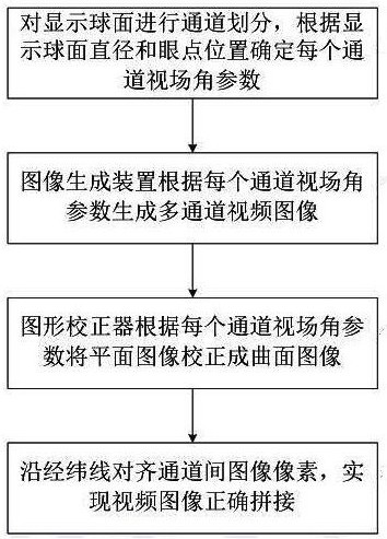
[0044] see figure 1 , a spherical video image correction method, comprising the following steps:
[0045] a. Set the LED lamp beads along the spherical longitude and latitude on the inner surface to form a display surface, and divide it into multiple display channels along the longitude direction, the pole area is divided into separate display channels along the latitude line, and the spherical display surface is divided into side channels and top or bottom. channel, determine the display field angle parameters of each channel according to the diameter of the display sphere and the position of the eye point;
[0046] b. The video image generation device generates a multi-channel rectangular graphic according to the display angle of view parameter, and synchronously outputs it to the back-end graphic corrector for geometric correction of the graphic from the plane to the spherical surface;
[0047] c. The graphic corrector converts each channel image generated by the video ima...
Embodiment 2
[0052] see figure 1 , a spherical video image correction method, comprising the following steps:
[0053] a. Set the LED lamp beads along the spherical longitude and latitude on the inner surface to form a display surface, and divide it into multiple display channels along the longitude direction, the pole area is divided into separate display channels along the latitude line, and the spherical display surface is divided into side channels and top or bottom. channel, determine the display field angle parameters of each channel according to the diameter of the display sphere and the position of the eye point;
[0054] b. The video image generation device generates a multi-channel rectangular graphic according to the display angle of view parameter, and synchronously outputs it to the back-end graphic corrector for geometric correction of the graphic from the plane to the spherical surface;
[0055] c. The graphic corrector converts each channel image generated by the video ima...
Embodiment 3
[0069] see figure 1 , a spherical video image correction method, comprising the following steps:
[0070] a. Set the LED lamp beads along the spherical longitude and latitude on the inner surface to form a display surface, and divide it into multiple display channels along the longitude direction, the pole area is divided into separate display channels along the latitude line, and the spherical display surface is divided into side channels and top or bottom. channel, determine the display field angle parameters of each channel according to the diameter of the display sphere and the position of the eye point;
[0071] b. The video image generation device generates a multi-channel rectangular graphic according to the display angle of view parameter, and synchronously outputs it to the back-end graphic corrector for geometric correction of the graphic from the plane to the spherical surface;
[0072] c. The graphic corrector converts each channel image generated by the video ima...
PUM
 Abstract
Description
Claims
Application Information
 - R&D
- Intellectual Property
- Life Sciences
- Materials
- Tech Scout
- Unparalleled Data Quality
- Higher Quality Content
- 60% Fewer Hallucinations
Browse by: Latest US Patents, China's latest patents, Technical Efficacy Thesaurus, Application Domain, Technology Topic, Popular Technical Reports.
© 2025 PatSnap. All rights reserved.Legal|Privacy policy|Modern Slavery Act Transparency Statement|Sitemap|About US| Contact US: help@patsnap.com