
Deramp-STAP moving target detection method based on Radon transform

A moving target detection and moving target technology, applied in the field of radar, can solve the problems of large amount of computation and cumbersome data processing process, and achieve the effect of reducing complexity, narrowing the range of data processing, and good focus

Pending Publication Date: 2021-01-15
NANJING UNIV OF SCI & TECH
View PDF6 Cites 3 Cited by
  • Summary
  • Abstract
  • Description
  • Claims
  • Application Information

AI Technical Summary

Problems solved by technology

However, this method needs to consider that KT is not suitable for Doppler ambiguity, so the author uses the method of Doppler center ambiguity number estimation based on minimum entropy to estimate the ambiguity number and realize linear distance walking correction, but the data The processing flow is cumbersome and the amount of calculation is large

Method used


Image

  • Deramp-STAP moving target detection method based on Radon transform
  • Deramp-STAP moving target detection method based on Radon transform
  • Deramp-STAP moving target detection method based on Radon transform

Examples


Embodiment

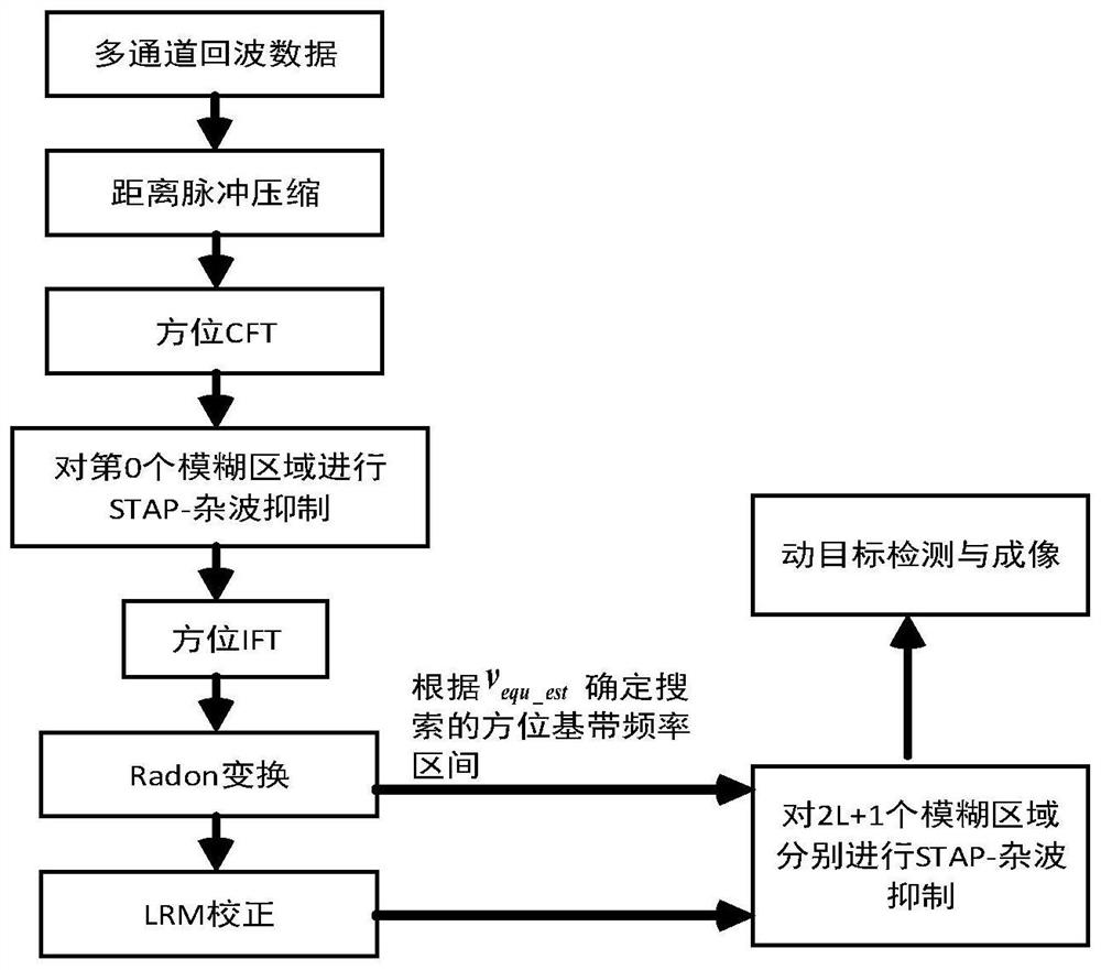
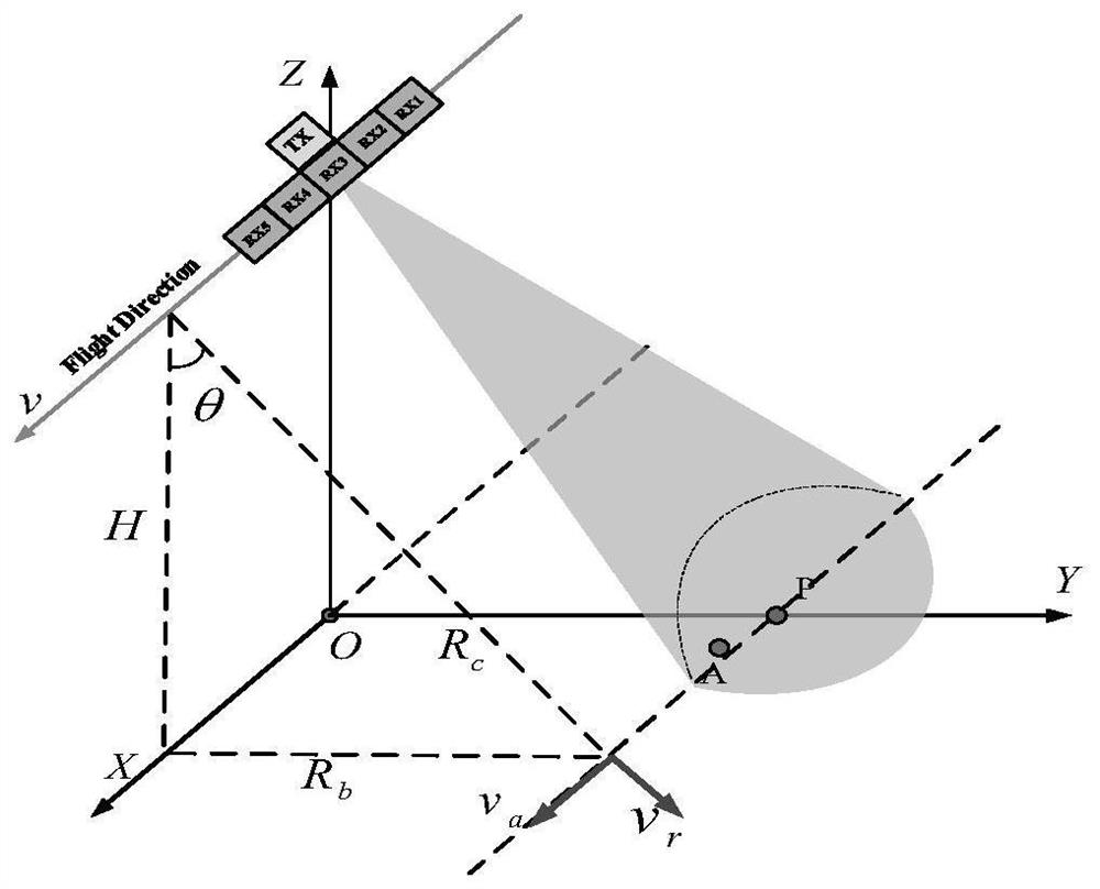
[0083] The present invention mainly adopts the mode of simulation experiment to verify, and the signal processing flow chart is as follows figure 1 As shown, the parameters required for the simulation are shown in Table 1, and the MC-SAR system structure model is shown in figure 2 As shown, the target scenario is as image 3 As shown, all steps and conclusions are verified on Matlab2010.

[0084] Table 1. Front and side looking MC-SAR system simulation parameter table

[0085] wavelength 0.03m Slope distance 70km platform height 30km platform speed 2000 pulse repetition frequency 2900Hz Doppler bandwidth 6928Hz pulse width 10us signal bandwidth 200MHz Sampling frequency 230MHz Array element spacing 0.5m

[0086] The present invention will be further described in detail with regard to specific embodiments below.

[0087] Step 1: Range-to-pulse compression. For any target in the imaging area, calculate the distanc...


PUM


Abstract

The invention discloses a Deramp-STAP moving target detection method based on Radon transform, and the method comprises the steps: obtaining the equivalent relative speed of a moving target through the introduction of Radon transform on the basis of a Deramp-STAP method, correcting the linear range walk of the moving target through the obtained equivalent relative speed, and reducing the CFT Doppler frequency range needing to be processed in a clutter inhibition process; and finally, employing the STAP method to realize accurate detection of the moving target. According to the method, the limitation that the number of channels of a radar imaging system is required to be greater than twice the azimuth Doppler ambiguity number in a conventional SAR-GMTI detection method is overcome, and theproblem of relatively large operand of a Deramp-STAP-based moving target detection method in the prior art is also solved.

Description

technical field [0001] The invention relates to the technical field of radar, in particular to a Radon transform-based Deramp-STAP moving target detection method. Background technique [0002] As an important milestone in the development of radar, radar synthetic aperture technology has the advantages of all-time, all-weather and high resolution. Since it was proposed, it has been widely concerned by researchers in the field of radar and remote sensing and has achieved rapid development. In recent years, with the continuous expansion of the application field of the SAR system, the conventional working system and imaging mode cannot meet the deepening application requirements. Therefore, further innovations have to be sought. Multi-channel SAR is proposed to deal with HRWS imaging scenarios. A new imaging regime. [0003] For the traditional SAR system, in order to obtain a large surveying scene without range ambiguity, it is necessary to transmit a low pulse repetition freq...

Claims


Application Information

Patent Timeline
Patent Type & Authority Applications(China)
IPC IPC(8): G01S13/90G01S7/41
CPCG01S13/9021G01S13/9029G01S7/414G01S7/415
Inventor 张婷婷谭珂苏卫民顾红陆星宇杨建超戴峥虞文超
Owner NANJING UNIV OF SCI & TECH
Learn More