Skirting line air conditioner indoor unit

An air-conditioning indoor unit and baseboard technology, which is applied in the field of air-conditioning, can solve the problems of uneven temperature in the height direction, small left and right air supply angles, and short air supply distance, so as to achieve uniform temperature distribution, improve heat exchange efficiency, and reduce fall. gray effect

Inactive Publication Date: 2021-01-15
CHUZHOU PRIMST IND DESIGN CO LTD
View PDF5 Cites 0 Cited by
  • Summary
  • Abstract
  • Description
  • Claims
  • Application Information

AI Technical Summary

Problems solved by technology

[0002] The indoor units of wall-mounted and cabinet-type air conditioners can be installed on the wall or at the root of the corner wall indoors. The indoor space occupied will affect the indoor layout. Because the installation position is relatively high, it can achieve better cooling effect, but in Due to the influence of air convection during heating, the hot air cannot effectively reach the human perception area, and the hot air blowing on the head for a long time will cause discomfort
Because the air outlet of the cabinet machine is not high and narrow, it is easy to blow directly to the human body. Long-term use will endanger the health of the body, and the left and right air supply angles are small, making the temperature of the living room space uneven
Although the air duct machine and wall-mounted machine solve the problem of not blowing people, the heating effect is not ideal, the hot air is difficult to reach the ground, the temperature in the room is uneven, the human body is not comfortable when using it, and it is easy to cause cold feet ; Common air source heat pump heaters have defects in the design of the air outlet, and the air supply distance is relatively short

Method used


Image

  • Skirting line air conditioner indoor unit
  • Skirting line air conditioner indoor unit
  • Skirting line air conditioner indoor unit

Examples


Embodiment Construction

[0024] The following will clearly and completely describe the technical solutions in the embodiments of the present invention with reference to the accompanying drawings in the embodiments of the present invention. Obviously, the described embodiments are only some, not all, embodiments of the present invention. Based on the embodiments of the present invention, all other embodiments obtained by persons of ordinary skill in the art without making creative efforts belong to the protection scope of the present invention.

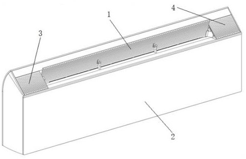
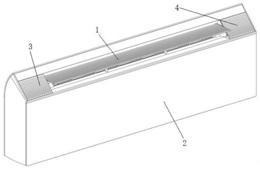
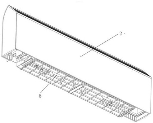
[0025] see Figure 1-6 , the present invention provides a technical solution: a baseboard air conditioner indoor unit, including a casing 2, the bottom of the casing 2 is provided with an air inlet, the top of the casing 2 is provided with an air outlet, and the top of the casing 2 is located The position of the air outlet is rotatably connected to the air deflector 1, and the top of the casing 2 is provided with a fresh air outlet 3 and an evaporator mist out...


PUM

PropertyMeasurementUnit
Slopeaaaaaaaaaa

Abstract

The invention discloses a skirting line air conditioner indoor unit. The skirting line air conditioner indoor unit comprises a machine shell, wherein an air inlet is formed in the bottom of the machine shell, an air outlet is formed in the top of the machine shell, an air guide plate is rotationally connected to the position, located at the air outlet, of the top of the machine shell, a fresh airoutlet and an evaporator mist outlet are sequentially formed in the top of the machine shell and located on the two sides of the air outlet, an air supply duct is arranged in the machine shell, a filter screen is arranged at the bottom of the machine shell and located at the position of the air inlet, an evaporator is arranged at the position, close to the air inlet, in the air supply duct, through-flow fan blades are rotationally connected into the air supply duct, a heating assembly is further arranged in the air supply duct, and a drainage groove is formed in the position, located below theevaporator, in the air supply duct. According to the skirting line air conditioner indoor unit, the air supply distance is increased through the design of a new air duct and an air outlet mode, meanwhile, direct blowing towards a human body is avoided, and the overall heating effect and use experience are improved.

Description

technical field [0001] The invention relates to the technical field of air conditioners, in particular to a baseboard air conditioner indoor unit. Background technique [0002] The indoor units of wall-mounted and cabinet-type air conditioners can be installed on the wall or at the root of the corner wall indoors. The indoor space occupied will affect the indoor layout. Because the installation position is relatively high, it can achieve better cooling effect, but in Due to the influence of air convection during heating, the hot air cannot effectively reach the human body's perception area, and the hot air blowing on the head for a long time will cause discomfort. Because the air outlet of the cabinet machine is not high and narrow, it is easy to blow directly to the human body. Long-term use will endanger the health of the body, and the left and right air supply angles are small, which makes the temperature of the living room space uneven. Although the air duct machine and...

Claims


Application Information

Patent Timeline
IPC IPC(8): F24F1/0057F24F1/0011F24F1/0087F24F1/0035F24F1/0073F24F13/14
CPCF24F1/0011F24F13/1426F24F2013/1433F24F1/0035F24F1/0057F24F1/0073F24F1/0087
Inventor 章吉哲黄运勇黄小林汪雨堃张旭
Owner CHUZHOU PRIMST IND DESIGN CO LTD
Why Eureka
Try Eureka