
An electric hydraulic brake

A technology of hydraulic brakes and electric power, which is applied in the direction of brake types, brake components, axial brakes, etc., and can solve the problems of asynchronous relative movement of two brake pads, decreased braking efficiency, lack of manual brake limit devices, etc. question

Active Publication Date: 2022-07-05
国网河南省电力公司柘城县供电公司
View PDF19 Cites 0 Cited by
  • Summary
  • Abstract
  • Description
  • Claims
  • Application Information

AI Technical Summary

Problems solved by technology

[0003] In some large equipment, electrohydraulic brakes are often installed to achieve braking operations. The existing electrohydraulic brakes mainly rely on the propeller to provide a power source to drive the contact between the two brake pads and the brake disc, which is achieved through friction. The principle of the braking function is similar to the disc brakes used in automobiles. The existing hydraulic brakes need to use a pusher to provide a power source for a long time to keep the two brake pads always in contact with the brake disc. Make contact to realize the braking function, but when the long-term braking operation is required, the pusher needs to work for a long time. At this time, it is very easy to cause damage to the pusher. It lacks a manual braking limit device to reduce the pressure of the pusher. lower lifespan
[0004] At the same time, in the existing braking device, two brake pads are generally used to brake the brake disc at the same time, but in actual use, the two brake pads need the power source provided by the pusher to realize the two brake pads. However, because the distances between the two brake pads and the pusher are not the same, the two brake pads may not be synchronized when they move relative to each other, resulting in two brake pads The degree of wear is different, resulting in a decrease in braking performance
Since the electrohydraulic brake itself uses friction to achieve braking operation, it will inevitably generate a lot of heat during the friction process between the brake pad and the brake disc. The overheating of the rotor, at this time, the braking force will be significantly reduced due to heat attenuation, which will cause longer braking time and affect the actual braking effect

Method used


Image

  • An electric hydraulic brake
  • An electric hydraulic brake
  • An electric hydraulic brake

Examples


Embodiment Construction

[0024] The technical solutions in the embodiments of the present invention will be clearly and completely described below with reference to the accompanying drawings in the embodiments of the present invention. Obviously, the described embodiments are only a part of the embodiments of the present invention, rather than all the embodiments. Based on the embodiments of the present invention, all other embodiments obtained by those of ordinary skill in the art without creative efforts shall fall within the protection scope of the present invention.

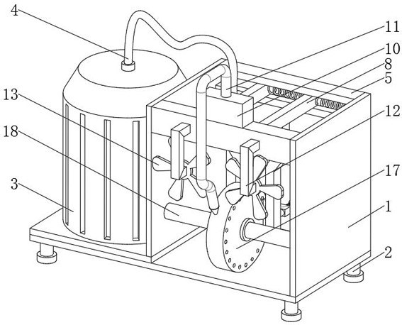
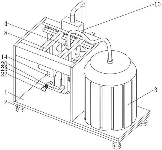
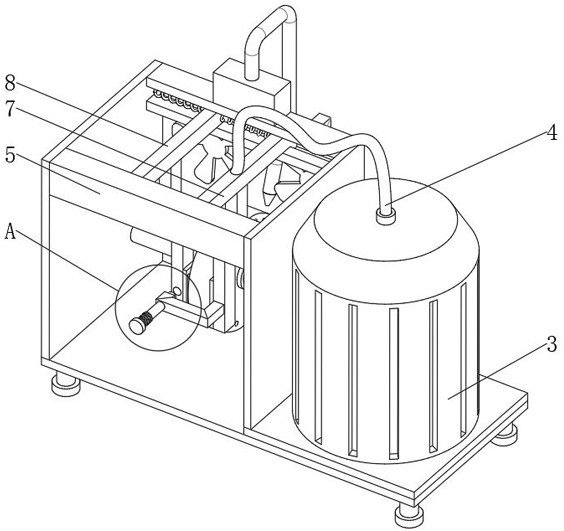
[0025] see Figure 1-6 , an electric hydraulic brake, including a frame 1, a fixed rod 5 is fixedly installed on the right side of the top of the frame 1, the number of the fixed rods 5 is two and is located on the front and rear sides of the frame 1, and the two fixed rods 5 are opposite to each other. The close end is provided with a chute 6, the inside of the chute 6 is movably installed with an active rod 7 and an auxiliary rod 8...


PUM


Abstract

The invention discloses an electric hydraulic brake, comprising a frame, a fixing rod is fixedly installed on the right side of the top of the frame, the number of the fixing rods is two and is located on the front and rear sides of the frame, the two The relatively close end of the fixed rod is provided with a chute, and an active rod and an auxiliary rod are movably installed inside the chute. In the electric hydraulic brake, a movable rod is movably sleeved at one end of the fixed frame, and a limit spring is movably sleeved on the movable rod. When the two brake pads are close to each other, the brake disc can be braked by Pulling the limit plate can drive the limit spring to be compressed and then drive the movable rod to move relative to the fixed hole. Position the movable rod just above the fixed hole and release the limit spring to drive the movable rod into the interior of the fixed hole to complete the movable clamping. , to complete the fixation between the two brake pads, thereby realizing the advantage that the brake can be manually limited.

Description

technical field [0001] The invention belongs to the technical field of hydraulic braking, and in particular relates to an electric hydraulic brake. Background technique [0002] Electro-hydraulic brakes are mechanical parts that stop or decelerate moving parts in machinery. Commonly known as brakes, brakes. The brake is mainly composed of a frame, a braking part and a control device. Some brakes are also equipped with automatic adjustment devices for brake clearance. In order to reduce the braking torque and structural size, the brake is usually installed on the high-speed shaft of the equipment, but large equipment with high safety requirements (such as mine hoists, elevators, etc.) should be installed on the low-speed shaft close to the working part of the equipment. superior. Some brakes are standardized and serialized and are manufactured by specialized factories for selection. [0003] In some large equipments, electro-hydraulic brakes are often installed to realiz...

Claims


Application Information

Patent Timeline
Patent Type & Authority Patents(China)
IPC IPC(8): F16D65/095F16D65/18F16D65/847F16D55/225F16D121/02
CPCF16D65/095F16D65/18F16D65/847F16D55/225F16D2121/02
Inventor 刘旭马召印刘伟屈新奇张效锋孙天坤李素花王海燕唐琨余沛莹
Owner 国网河南省电力公司柘城县供电公司
Learn More