
High-temperature and high-pressure vertical pipeline pump

A vertical pipeline, high temperature and high pressure technology, applied in the direction of non-variable pumps, non-volume pumps, pumps, etc., can solve the problems of cavitation, short service life of bearings, high temperature of bearing box oil chamber, etc., to prevent bearing temperature The effect of raising and lowering the load and prolonging the service life

Pending Publication Date: 2022-06-17
YANTAI LONGGANG PUMP IND CO LTD
View PDF9 Cites 0 Cited by
  • Summary
  • Abstract
  • Description
  • Claims
  • Application Information

AI Technical Summary

Problems solved by technology

The temperature of the conveying medium is 230℃~370℃, the inlet pressure is 8~12MPa, and the outlet pressure is ≥12Mpa. In the range from the minimum continuous stable flow rate to the maximum rated flow rate, the difference between NPSHa and NPSHr is ≤2m. This harsh working condition is conventional vertical pipeline The pump simply increases the thickness of the pressure-bearing wall or the water cooling of the outer cladding bearing is not enough. After a period of use, the flow rate, lift and efficiency of the above-mentioned improved conventional vertical pipeline pump will all decrease, and cavitation and vibration will occur at the same time. and other phenomena
Due to the high temperature of the medium and the high inlet pressure, the gap between the mouth ring and the friction pair will become smaller due to temperature expansion, the service life of the bearing will be shorter, and the temperature of the oil chamber of the bearing box will be high. The equipment will be damaged in a short time and cannot operate normally. , seriously affecting the safe operation and production of the device

Method used


Image

  • High-temperature and high-pressure vertical pipeline pump
  • High-temperature and high-pressure vertical pipeline pump
  • High-temperature and high-pressure vertical pipeline pump

Examples


specific Embodiment approach

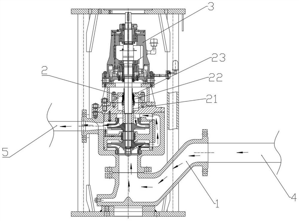
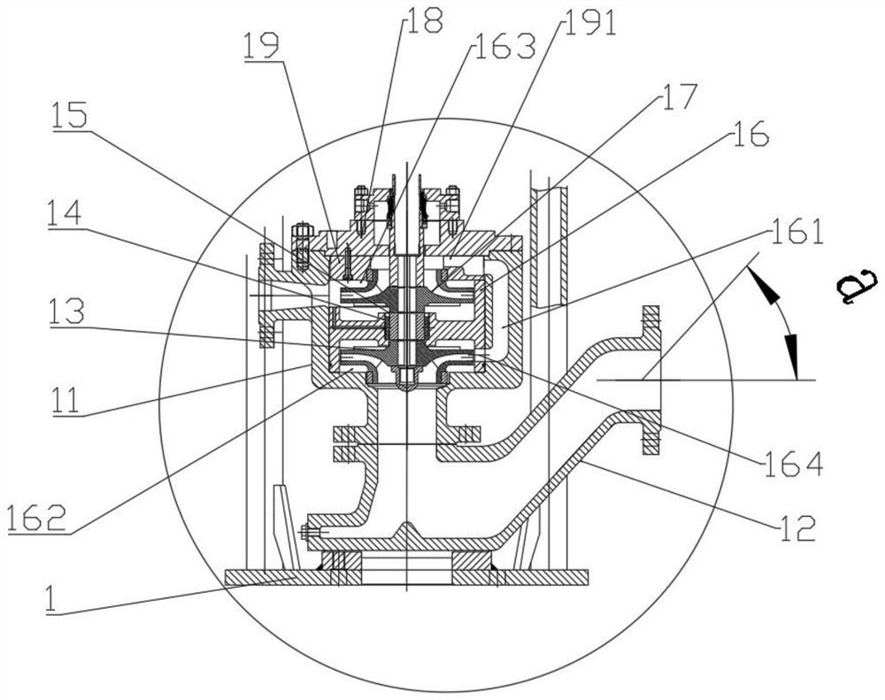
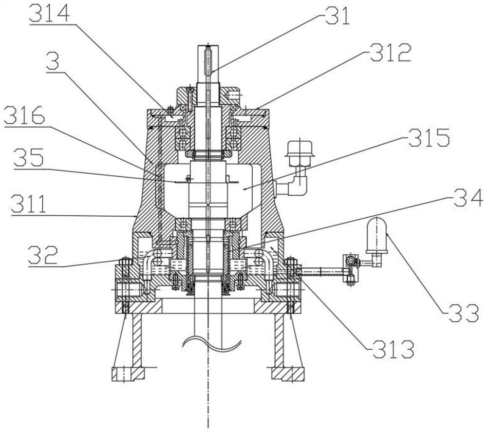
[0030] see Figure 1-Figure 4 , a high temperature and high pressure vertical pipeline pump, including a flow unit 1, a sealing unit 2 and a rotating shaft unit 3, the flow unit 1 is connected to the input pipe 4 and the output pipe 5, and provides the power for the flow of the medium in the pipeline, The sealing unit 2 is arranged between the overcurrent unit 1 and the rotating shaft unit 3, connects the overcurrent unit 1 and the rotating shaft unit 3 and isolates the overcurrent unit 1 and the rotating shaft unit 3, and the rotating shaft unit 3 includes The pump shaft 31 passes through the sealing unit 2 and is connected to the centrifugal impeller arranged in the flow unit 1, and the other end extends out of the rotating shaft unit 3 and is connected to the driving device. The driving device drives the centrifugal impeller through the pump shaft 31. The impeller rotates to pressurize the flow of the medium through the in-line pump.

[0031] see figure 2 , the overflow ...


PUM


Abstract

A high-temperature and high-pressure vertical pipeline pump comprises an overflowing unit, a sealing unit and a rotating shaft unit, the overflowing unit is connected with an input pipe and an output pipe and provides flowing power for media in a pipeline, and the sealing unit is arranged between the overflowing unit and the rotating shaft unit. The connecting unit is connected with the overflowing unit and the rotating shaft unit and isolates the overflowing unit from the rotating shaft unit, the rotating shaft unit comprises a pump shaft, one end of the pump shaft is connected with a centrifugal impeller arranged in the overflowing unit, the other end of the pump shaft is connected with a driving device, and the driving device drives the centrifugal impeller to rotate through the pump shaft. The medium passing through the pipeline pump is made to flow. The pipeline pump can convey media with the temperature ranging from 230 DEG C to 370 DEG C, the inlet pressure ranges from 8 MPa to 12 MPa, and the outlet pressure is larger than or equal to 12 MPa.

Description

technical field [0001] The invention relates to the field of pipeline pump manufacturing, in particular to the above-mentioned high temperature and high pressure vertical pipeline pump. Background technique [0002] Conventional vertical pipeline pumps have the characteristics of simple structure and light weight, and are mainly used in various fields of clean water and pipeline transportation such as industrial and urban water supply and drainage, high-rise building pressurized water supply and fire pressurization. However, in the above application fields, there is basically no need to consider the harsh working conditions of high temperature and high pressure. The conventional vertical pipeline pump only needs to consider the economy and practicability of the product, and it is not considered in the refining and hydrocracking systems. The need to withstand high temperature, high pressure and other conditions makes conventional vertical pipeline pumps unable to meet the req...

Claims


Application Information

Patent Timeline
IPC IPC(8): F04D1/08F04D7/06F04D29/041F04D29/06F04D29/18F04D29/22F04D29/58F04D29/62
CPCF04D1/08F04D7/06F04D29/185F04D29/2222F04D29/628F04D29/2266F04D29/041F04D29/061F04D29/5886
Inventor 许文超刘先盛高兴振郑剑平王殿远
Owner YANTAI LONGGANG PUMP IND CO LTD
Learn More