
Visual horizontal annulus rock debris migration simulation method

A simulation method and horizontal ring technology, applied in teaching models, earth-moving drilling, wellbore/well components, etc., can solve the problems of not considering the actual annular well wall roughness, complex structure, inability to simulate more realistically, etc. Ensure the reliability of the experiment, the accuracy of the experimental results, and the effect of easy observation

Inactive Publication Date: 2021-01-15
BC P INC CHINA NAT PETROLEUM CORP +1
View PDF9 Cites 2 Cited by
  • Summary
  • Abstract
  • Description
  • Claims
  • Application Information

AI Technical Summary

Problems solved by technology

[0004] The horizontal well cuttings migration simulation experimental device disclosed in this patent document has a relatively complex structure. The drill pipe is replaced by a PVC pipe, and the roughness of the actual annular well wall is not considered, so it cannot simulate the actual working conditions more realistically.

Method used


Image

  • Visual horizontal annulus rock debris migration simulation method
  • Visual horizontal annulus rock debris migration simulation method

Examples


Embodiment 1

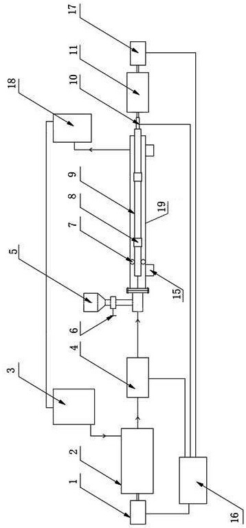
[0035] see figure 1 , a method for simulating the movement of debris in a visualized horizontal annulus, comprising the following steps:

[0036] a. Inject fluid into the annulus of the simulated wellbore 19 of the visualized horizontal annulus cuttings migration simulation equipment through the drilling fluid device, simulating the drilling fluid in the horizontal annulus of the horizontal well;

[0037] b. Regulate the amount of cuttings injected into the cuttings tank 5 by the feed control valve 6, record the amount of cuttings injected per minute, according to the readings of the liquid flow meter 4, the weight of cuttings in the cuttings separator 18, and the readings of the torque sensor 10 , The readings of the first frequency converter 1, the readings of the second frequency converter 17, the eccentricity of the drill pipe 9, the cuttings migration track and the cuttings bed start-up and settlement distance again, and analyze the influence of different cuttings amounts...

Embodiment 2

[0044] see figure 1 , a method for simulating the movement of debris in a visualized horizontal annulus, comprising the following steps:

[0045] a. Inject fluid into the annulus of the simulated wellbore 19 of the visualized horizontal annulus cuttings migration simulation equipment through the drilling fluid device, simulating the drilling fluid in the horizontal annulus of the horizontal well;

[0046] b. Regulate the amount of cuttings injected into the cuttings tank 5 by the feed control valve 6, record the amount of cuttings injected per minute, according to the readings of the liquid flow meter 4, the weight of cuttings in the cuttings separator 18, and the readings of the torque sensor 10 , The readings of the first frequency converter 1, the readings of the second frequency converter 17, the eccentricity of the drill pipe 9, the cuttings migration track and the cuttings bed start-up and settlement distance again, and analyze the influence of different cuttings amounts...

Embodiment 3

[0054] see figure 1 and figure 2 , a method for simulating the movement of debris in a visualized horizontal annulus, comprising the following steps:

[0055] a. Inject fluid into the annulus of the simulated wellbore 19 of the visualized horizontal annulus cuttings migration simulation equipment through the drilling fluid device, simulating the drilling fluid in the horizontal annulus of the horizontal well;

[0056] b. Regulate the amount of cuttings injected into the cuttings tank 5 by the feed control valve 6, record the injection amount of cuttings per minute, according to the readings of the liquid flow meter 4, the weight of cuttings in the cuttings separator 18, and the readings of the torque sensor 10 , The readings of the first frequency converter 1, the readings of the second frequency converter 17, the eccentricity of the drill pipe 9, the cuttings migration trajectory and the cuttings bed start-up and settlement distance again, and analyze the influence of diffe...


PUM


Abstract

The invention discloses a visual horizontal annulus rock debris migration simulation method, and belongs to the technical field of petroleum drilling simulation experiments. The visual horizontal annulus rock debris migration simulation method is characterized by comprising the following steps of a, injecting liquid into an annulus of a simulation wellbore to simulate drilling fluid in a horizontal annulus of a horizontal well; b, regulating and controlling the rock debris injection amount of a rock debris tank through a feeding control valve, and analyzing the influence of different rock debris amounts on rock debris migration; c, adjusting the displacement of the drilling fluid, and analyzing the influence of different drilling fluid return speeds on rock debris migration; d, adjusting arotary eccentric device of a drill rod, and analyzing the influence of different eccentricities on rock debris migration; e, analyzing the influence of different rotating speeds of the drill rod on rock debris migration by adjusting the rotating speed of the drill rod; and f, analyzing the influence of the rock debris with different physical properties on the migration of the rock debris by injecting the rock debris with different physical properties. According to the visual horizontal annulus rock debris migration simulation method, the principle is reliable, operation is easy and convenient, and the migration situation of rock debris under various working conditions of the large-displacement horizontal annulus section of the horizontal well can be simulated more truly.

Description

technical field [0001] The invention relates to the technical field of simulated oil drilling experiments, in particular to a method for simulating the migration of rock cuttings in a visualized horizontal annular space. Background technique [0002] With the increasingly harsh oil drilling and production conditions and the continuous development of drilling and production technology, horizontal well drilling has become an important means of modern oil and gas exploration and development in order to achieve efficient development of old oil fields and special oil reservoirs and increase single well productivity. However, due to the characteristics of the horizontal section of the horizontal well, it is naturally difficult for cuttings to migrate. In the large-displacement horizontal annular section, the drill string is close to the lower hole wall due to its own gravity to form an eccentric annulus, and cuttings are easily trapped at the drill pipe joint. And the lower part o...

Claims


Application Information

Patent Timeline
IPC IPC(8): E21B21/00E21B47/00G09B25/02
CPCE21B21/00E21B47/00G09B25/02
Inventor 张继川李皋白璟邓虎肖东万夫磊陈一健明显森李雷黄崇君吴磊李睿毛斌
Owner BC P INC CHINA NAT PETROLEUM CORP
Learn More