
Anti-falling beam shock isolation device convenient for shock resistance of bridge

A technology for anti-falling beams and shock isolation, applied in bridges, bridge parts, bridge construction, etc., can solve problems such as unsatisfactory cushioning and shock absorption performance, achieve stable and fast installation, prevent damage, and speed up bridge construction

Inactive Publication Date: 2021-01-15
温州顺启建筑有限公司
View PDF6 Cites 2 Cited by
  • Summary
  • Abstract
  • Description
  • Claims
  • Application Information

AI Technical Summary

Problems solved by technology

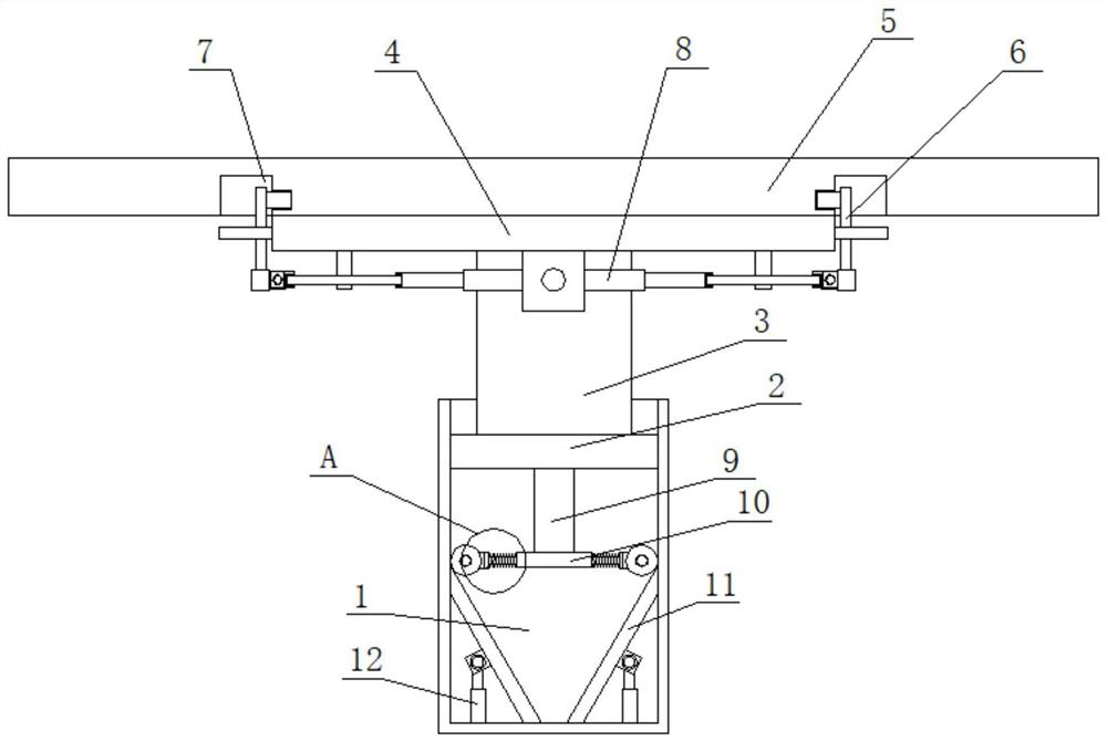
[0004] In view of this, in order to solve the problem that the buffering and shock absorption performance of the beam body is not ideal after the anti-collision block is installed, the present invention provides an anti-falling beam isolation device that is convenient for the earthquake resistance of the bridge

Method used


Image

  • Anti-falling beam shock isolation device convenient for shock resistance of bridge
  • Anti-falling beam shock isolation device convenient for shock resistance of bridge
  • Anti-falling beam shock isolation device convenient for shock resistance of bridge

Examples


Embodiment Construction

[0028]The following describes the implementation of the present invention through specific specific examples. Those skilled in the art can easily understand other advantages and effects of the present invention from the content disclosed in this specification. The present invention can also be implemented or applied through other different specific embodiments, and various details in this specification can also be modified or changed based on different viewpoints and applications without departing from the spirit of the present invention. It should be noted that the illustrations provided in the following embodiments are only illustrative to illustrate the basic concept of the present invention. In the case of no conflict, the following embodiments and features in the embodiments can be combined with each other.

[0029]Among them, the drawings are only used for exemplary description, and they are only schematic diagrams rather than physical drawings, and cannot be understood as a limi...


PUM


Abstract

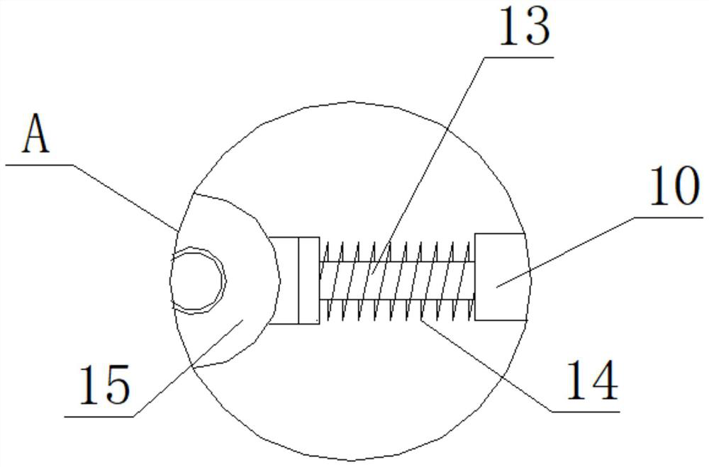
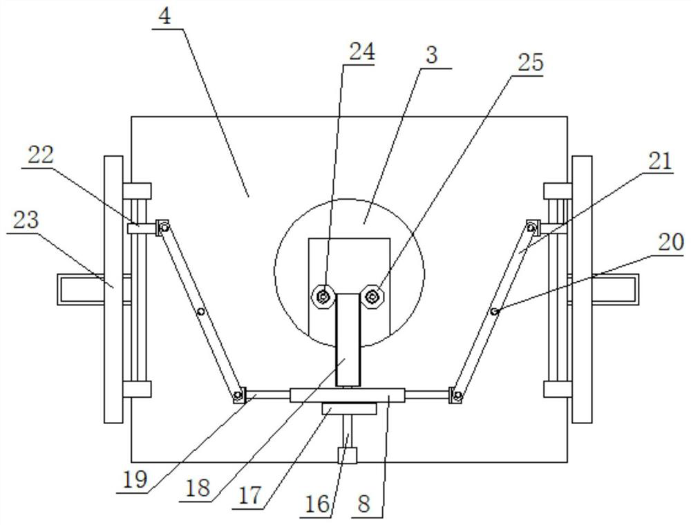
The invention belongs to the field of bridges, and particularly relates to an anti-falling beam shock isolation device convenient for shock resistance of a bridge. The top end of a supporting column in sliding connection in a supporting cover extends to the upper portion of the supporting cover, two threaded pipes are symmetrically and rotationally connected in a mounting groove in one side of thesupporting column, and the directions of threads on two threaded columns in each threaded pipe are opposite; two sliding holes are symmetrically formed in the bearing plate, two positioning grooves are symmetrically formed in the bottom of the bridge plate, the top ends of the two threaded columns extend into the two sliding holes correspondingly and are fixedly provided with positioning columnscorrespondingly, and the top ends of the two positioning columns extend into the two positioning grooves correspondingly and are clamped with the two positioning grooves correspondingly. The two positioning columns are slidably connected with the two sliding holes correspondingly, a threaded connection screw on one side of the bearing plate is in transmission connection with the two threaded pipescorrespondingly, clamping plates are slidably connected to the two sides of the bearing plate correspondingly, the two clamping plates are both clamped to the bridge plate, and the two clamping plates are both in transmission connection with the screw; the anti-falling beam shock isolation device can be stably and rapidly installed, and three-stage damping can be conducted on the bridge plate.

Description

Technical field[0001]The invention belongs to the technical field of bridges, and relates to an anti-drop beam seismic isolation device which is convenient for bridge seismic resistance.Background technique[0002]In recent years, with the rapid development of bridges and construction projects in my country, various new structural forms and functions of construction projects have continued to emerge. my country has proposed a special mission for bridge engineering. The 5.12 Wenchuan earthquake caused huge losses. The nearby infrastructure has been severely damaged, and bridge damage is particularly serious. Falling beam damage, collision between beams, and block damage are the main forms of damage to the bridge and obstructing traffic. This requires the installation of seismic isolation and anti-falling beam devices.[0003]At present, most of the used bridge anti-dropping devices rely on the anti-collision block installed on the platform and arranged in the transverse direction to coop...

Claims


Application Information

Patent Timeline
IPC IPC(8): E01D19/00
CPCE01D19/00
Inventor 孔虎李旺李玉辉
Owner 温州顺启建筑有限公司
Learn More