
A kind of compound and organic electroluminescent device

A compound and luminescent technology, applied in the direction of electric solid-state devices, organic chemistry, luminescent materials, etc., can solve the problems of insufficient development of organic electroluminescent materials and backward panel manufacturing enterprises, so as to improve service life and luminous efficiency, and increase molecular weight , the effect of improving life

Active Publication Date: 2021-03-26
NANJING TOPTO MATERIALS CO LTD
View PDF3 Cites 0 Cited by
  • Summary
  • Abstract
  • Description
  • Claims
  • Application Information

AI Technical Summary

Problems solved by technology

[0005] As far as the actual needs of the current organic electroluminescent industry are concerned, the development of organic electroluminescent materials is far from enough, lagging behind the requirements of panel manufacturers

Method used

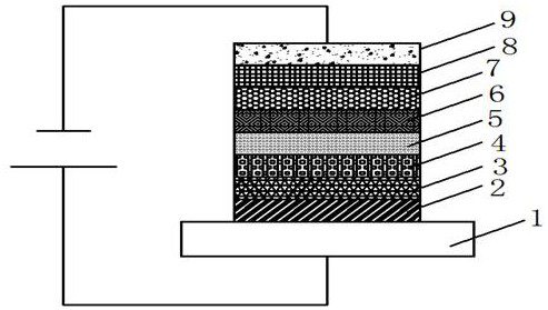

Image

  • A kind of compound and organic electroluminescent device
  • A kind of compound and organic electroluminescent device
  • A kind of compound and organic electroluminescent device

Examples


Embodiment 1

[0051]

[0052] The preparation method of compound 1 is as follows:

[0053]

[0054]S1: Under nitrogen protection, compound 1-a (10g, 226.06g / mol, 44.24mmol), compound 1-b (1.1eq, 11.84g, 243.30g / mol, 48.66mmol), sodium tert-butoxide (1.1eq , 4.68g, 96.1g / mol, 48.66mmol), tris(dibenzylideneacetone)dipalladium (0.05eq, 2.02g, 915g / mol, 2.21mmol), tri-tert-butylphosphine (0.05eq, 0.45g, 202.32g / mol, 2.21mmol), toluene (100ml) were added to the reaction flask, after the addition was completed, the temperature was raised to reflux for 5 hours, after the reaction was completed, the temperature was lowered to room temperature, and water (100ml) was added and stirred for 15 minutes to obtain the filtrate, which was passed through diatom The organic phase was obtained by liquid separation after soil filtration. The organic phase was dried with anhydrous magnesium sulfate and spin-dried, and purified by column chromatography to obtain compound 1-c (12.12g, yield 63.3%), ESI-MS (...

Embodiment 2

[0057]

[0058] The preparation method of compound 3 is as follows:

[0059]

[0060] The preparation method is basically the same as in Example 1, the difference is that compound 1-b is replaced by compound compound 2-b, and the reaction gives compound 3 (yield 71.7%), ESI-MS (m / z) (M+): theoretical value 645.76 , measured value 646.30, elemental analysis results (molecular formula C45H23D5N4O): theoretical value C, 83.70; H, 5.15; N, 8.68; O, 2.48; measured value C, 83.70; H, 5.15; N, 8.68; O, 2.48.

Embodiment 3

[0062]

[0063] The preparation method of compound 4 is as follows:

[0064]

[0065] The preparation method is basically the same as in Example 1, the difference is that compound 3-b is used to replace compound 1-b, and the reaction gives compound 4 (yield 71.5%), ESI-MS (m / z) (M+): theoretical value 645.76 , measured value 646.62, element analysis results (molecular formula C45H23D5N4O): theoretical value C, 83.70; H, 5.15; N, 8.68; O, 2.48; measured value C, 83.70; H, 5.14; N, 8.68; O, 2.48.


PUM

PropertyMeasurementUnit
thicknessaaaaaaaaaa
thicknessaaaaaaaaaa

Abstract

The invention discloses a compound and an organic electroluminescence device. Its structural formula is shown in formula 1: wherein, R1, R2, and R3 are the same or different, and each independently represents hydrogen, phenyl, biphenyl, terphenyl, Naphthyl, anthracenyl, phenanthrenyl; the phenyl, biphenyl, terphenyl, naphthyl, anthracenyl, phenanthrenyl are unsubstituted or at least one hydrogen is replaced by deuterium, C1-C4 alkyl or benzene The group obtained by substituting the base; R4 is phenyl, biphenyl, terphenyl, naphthyl, anthracenyl, phenanthrene; the phenyl, biphenyl, terphenyl, naphthyl, anthracenyl, phenanthrene The group is unsubstituted or wherein at least one hydrogen is substituted by deuterium, C1-C4 alkyl or phenyl; X is O or S; Y1, Y2, Y3 are the same or different, each independently being N or CH, and Y1, Y2, and Y3 are not CH at the same time, the compound molecule has bipolar characteristics, and has the characteristics of transporting electrons and holes at the same time, which further improves the service life and luminous efficiency of the device.

Description

technical field [0001] The invention relates to the technical field of organic electroluminescence, in particular to a compound and an organic electroluminescence device. Background technique [0002] OLED is a kind of device that utilizes multi-layer organic thin film structure to generate electroluminescence. It is easy to manufacture and only requires low driving voltage. These main features make OLED very prominent in the application of flat-panel displays. OLED displays are thinner and thinner than LCDs, have high brightness, low power consumption, fast response, high definition, good flexibility, and high luminous efficiency, which can meet the new needs of consumers for display technology. More and more display manufacturers around the world have invested in research and development, which has greatly promoted the industrialization process of OLED. [0003] Currently, an OLED device consists of a substrate, cathode, anode, hole injection layer (HIL), electron injecti...

Claims


Application Information

Patent Timeline
Patent Type & Authority Patents(China)
IPC IPC(8): C07D405/14C09K11/06H01L51/54H01L51/50
CPCC07D405/14C09K11/06C07B2200/05C09K2211/1059C09K2211/1029C09K2211/1088C09K2211/1044H10K85/615H10K85/622H10K85/654H10K85/6574H10K85/6572H10K50/12
Inventor 钱超许军
Owner NANJING TOPTO MATERIALS CO LTD
Learn More