
Energy conversion device and vehicle

An energy conversion device and electric energy technology, applied in the field of vehicles, can solve the problems of large volume, complex structure of the motor drive and charging system, and high cost

Active Publication Date: 2021-01-15
BYD CO LTD
View PDF4 Cites 3 Cited by
  • Summary
  • Abstract
  • Description
  • Claims
  • Application Information

AI Technical Summary

Problems solved by technology

[0005] The purpose of this application is to provide an energy conversion device and a vehicle, aiming to solve the problems of the existing technology in the motor drive and charging system with complex overall structure, low integration, large volume and high cost

Method used


Image

  • Energy conversion device and vehicle
  • Energy conversion device and vehicle
  • Energy conversion device and vehicle

Examples


Embodiment approach

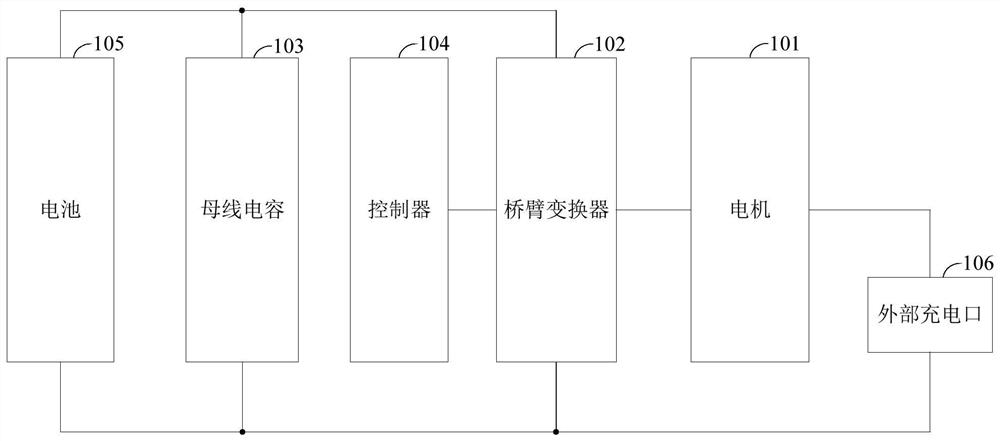
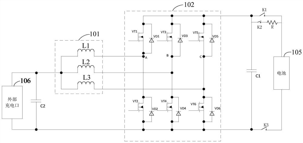
[0071] As an embodiment, the external charging port is a DC charging port, the external power supply is a DC power supply device, the working cycle of the driving and charging circuit includes a first working stage and a second working stage; the motor coil includes a first coil and a second coil, The bridge arm converter 102 includes a first bridge arm connected to the first coil and a second bridge arm connected to the second coil.

[0072] In the first working stage, the controller 104 controls the conduction time and duration of the first bridge arm and the second bridge arm according to the power to be driven by the motor and the power to be charged by the battery, so that the electric energy of the DC power supply equipment passes through the first coil and the second bridge arm. The first bridge arm flows back to the DC power supply equipment, and at the same time, the electric energy on the bus capacitor 103 flows back to the bus capacitor 103 after passing through the ...


PUM


Abstract

The invention provides an energy conversion device and a vehicle, the energy conversion device comprises a motor coil of a motor, a bridge arm converter, a bus capacitor connected in parallel with thebridge arm converter and a controller connected with the bridge arm converter, and when the energy conversion device is connected to an external power supply, according to the to-be-driven power of the motor and the to-be-charged power of the external battery, the controller controls the bridge arm converter to enable the electric energy of the external power supply to flow to the driving and charging circuit, and the current of the driving and charging circuit is adjusted to enable the external power supply to drive the motor to output the driving power while charging the battery; accordingto the application, the battery can be charged while the external power supply drives the motor to output the driving power only by controlling the bridge arm converter to adjust the current flowing to the driving and charging circuit from the external power supply, so that the problems of complex overall structure, low integration level, large size and high cost of a motor driving and charging system in the prior art are solved.

Description

technical field [0001] The present application relates to the technical field of vehicles, in particular to an energy conversion device and a vehicle. Background technique [0002] In recent years, with the continuous development of electric vehicle technology, the market's acceptance of electric vehicles has continued to increase, and battery charging and motor drive, as the core technologies in electric vehicles, have received widespread attention. At present, the battery charging circuit and the motor drive circuit in the existing electric vehicles on the market are separated. The battery charging circuit is used to charge the battery of the electric vehicle, and the motor drive circuit is used to drive the motor of the electric vehicle. intervene independently of each other. [0003] However, although two circuits can be used to complete the battery charging and motor driving process of electric vehicles, since the two circuits in the above method do not interfere with ...

Claims


Application Information

Patent Timeline
IPC IPC(8): B60L53/00B60L15/00B60L15/20H02J7/02H02J7/00
CPCB60L53/00B60L15/007B60L15/20H02J7/02Y02T10/72Y02T10/64B60L53/24H02J2207/40H02J2207/20H02J2310/48H02J7/0068B60L2240/425B60Y2200/91
Inventor 闫磊李吉成雷野谢飞跃郑思佳
Owner BYD CO LTD
Learn More