


Quick Research
Generate reliable direction feasibility study reports for your R&D in just a few steps.

Technical Q&A
Discover and master advanced knowledge NOW. Basics, ideas, possibilities, all at once.

Find Solutions
As an expert in R&D theories, this can generate solutions to your technical problems instantly.

Evaluate Feasibility
Analyze your overall solution with one click, know your potential R&D risks in advance.

Monitor Landscape
Get weekly tech updates, stay abreast of the latest tech innovations and key insights.
A driving device for an energy-saving new energy vehicle
A technology of new energy vehicles and driving devices, which is applied in the direction of electric vehicles, electromechanical devices, electric vehicle charging technology, etc., can solve the problems of reducing the generator, reducing the functionality of the driving device, and fixing the braking effect, so as to improve the control effect and improve Energy-saving effect, the effect of increasing the speed reduction effect
- Summary
- Abstract
- Description
- Claims
- Application Information
AI Technical Summary
Problems solved by technology
Method used
Image

Examples
Embodiment 1
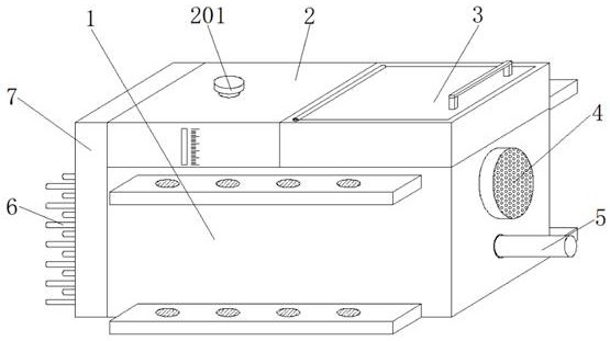
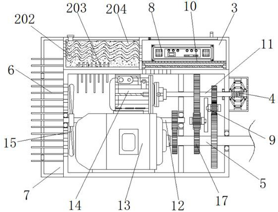
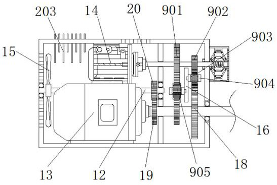
[0034] Example 1, such as Figure 1-4 As shown, when the driving device for the new energy vehicle needs to be braked at a low speed, after the driver of the vehicle lightly steps on the foot brake, the first group of electric pneumatic cylinders 906 are controlled through the console of the vehicle to push a group of U-shaped frames 904, so that The second transmission gear 905 meshes with the first large gear 901 and the second small gear 17 respectively, thereby driving the rotating shaft of the generator 14 to rotate, and while reducing the speed of the first drive shaft 5, the generator 14 is also used to generate electricity, and through the inverter The converter 8 converts the electricity generated by the generator 14 and then transfers it to the storage battery of the automobile.
Embodiment 2
[0035] Example 2, such as Figure 1-3 As shown, when the driving device for the new energy vehicle normally drives the vehicle, the driving motor 13 drives the fan 15 on the rotating rod 12 to rotate through the cooperation of the first connecting gear 19 and the second connecting gear 20, so that the main body box 1 The air with heat inside is blown into the inside of the connecting chamber 7, part of the heat of the hot air is absorbed by the second heat conducting rod 6 and dissipated to the outside, and when the hot air passes through the heat exchange tube 202, a large amount of heat is stored The coolant inside the water tank 204 is absorbed, and then the cooled air is blown into the inside of the installation chamber 3, and the inverter 8 is blown to cool down and then flows back into the inside of the main box 1, and the driving motor inside the main box 1 13 and the generator 14 carry out wind cooling to form air circulation flow, and part of the heat inside the main ...
Embodiment 3
[0036] Example 3, such as figure 1 , 2 , 3, 4 and 6, when the driving device of the new energy vehicle needs to brake at high speed, the driver will step on the foot brake to the bottom, so as to control the second group of electric pneumatic cylinders 906 to extend to the maximum through the console of the car. Long, so that the first transmission gear 903 meshes with the first small gear 902 and the second large gear 18 respectively, driving the second drive shaft 11 to rotate, while the first group of electro-pneumatic cylinders 906 is shortened, and the second transmission gear 905 is no longer in contact with the second transmission gear 905. The large gear 901 meshes with the second small gear 17. Since the gear diameter of the second large gear 18 is larger than that of the first small gear 902, the speed of the second drive shaft 11 will be further increased, and the speed of the rotating shaft of the generator 14 will be increased. When the generator 14 produces more...
PUM
 Abstract
Description
Claims
Application Information
 - R&D Engineer
- R&D Manager
- IP Professional
- Industry Leading Data Capabilities
- Powerful AI technology
- Patent DNA Extraction
Browse by: Latest US Patents, China's latest patents, Technical Efficacy Thesaurus, Application Domain, Technology Topic, Popular Technical Reports.
© 2024 PatSnap. All rights reserved.Legal|Privacy policy|Modern Slavery Act Transparency Statement|Sitemap|About US| Contact US: help@patsnap.com