
Clamping device for forklift accessory machining

A technology for clamping devices and accessories, applied in positioning devices, metal processing equipment, metal processing mechanical parts, etc., can solve the problems of the outer surface of hardware accessories, such as depression, unfavorable accessories production and processing operations, and unfavorable accessories production and processing efficiency. Good fixing effect, good clamping and fixing effect, and the effect of improving convenience

Inactive Publication Date: 2021-01-15
湖南川田机械制造有限公司
View PDF8 Cites 2 Cited by
  • Summary
  • Abstract
  • Description
  • Claims
  • Application Information

AI Technical Summary

Problems solved by technology

[0002] Accessories refer to the machine parts or parts made of them, as well as some small hardware products, which can be used alone or as auxiliary appliances, such as tools, parts, daily hardware, construction and security products, etc. Most of the small hardware products are not final consumer goods. Instead, as ancillary products, semi-finished products and tools used in the production process of industrial manufacturing, hardware accessories need to be polished on their outer surfaces during processing, and clamping devices need to be used to fix them during the grinding process; now Nowadays, most of the clamping devices often think that the pressure generated during the fixation cannot be controlled in the process of clamping the hardware accessories, which makes the outer surface of the hardware accessories concave during the processing process, and at the same time, the hardware accessories are produced during grinding. The debris will splash around under the force of grinding, and when it comes into contact with the skin of the staff, it is easy to cause problems such as scratches on the skin of the staff
[0003] For example, the Chinese patent application number is 201920924384.4, a clamping device for hardware accessories processing, which is basically described as: including a fixed base, one side of the bottom of the fixed base is fixedly installed with supporting legs, and the fixed base One side of the top is fixedly installed with a fixed rod, the outer surface of the fixed rod is movably sleeved with a protective plate, the other side of the front of the protective plate is fixedly installed with a fixed block, and one side of the fixed block is fixedly installed with a first connection One side of the front side of the first connection block is threaded with a bolt, and one end of the bolt penetrates to the back of the first connection block, and one side of the top of the fixed base is movably connected with a moving plate, and one side of the top of the moving plate is fixedly installed with a moving block, and the top of one side of the moving block is fixedly installed with a second connecting block, and one end of the second connecting block is fixedly installed with a limiting splint. The bottom is movably connected with a movable block on one side of the supporting leg, and one side of the bottom of the movable block is movably socketed with a threaded rod, and one end of the threaded rod runs through the movable block, the fixed machine base and the moving plate from bottom to top in sequence, and the threaded rod One end of the rod is threaded with a threaded sleeve on the top of the moving plate, and a grinding block is placed on the top of the fixed machine base. The clamping device used for processing hardware accessories clamps the accessories through the limit splint, but the clamp The holding method has a poor clamping effect on special-shaped accessories, and it is difficult to more firmly clamp special-shaped accessories, which is not conducive to better production and processing of accessories, and is not conducive to better processing of accessories. Improvement of spare parts production and processing efficiency

Method used


Image

  • Clamping device for forklift accessory machining
  • Clamping device for forklift accessory machining
  • Clamping device for forklift accessory machining

Examples


Embodiment 1

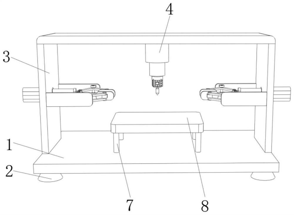
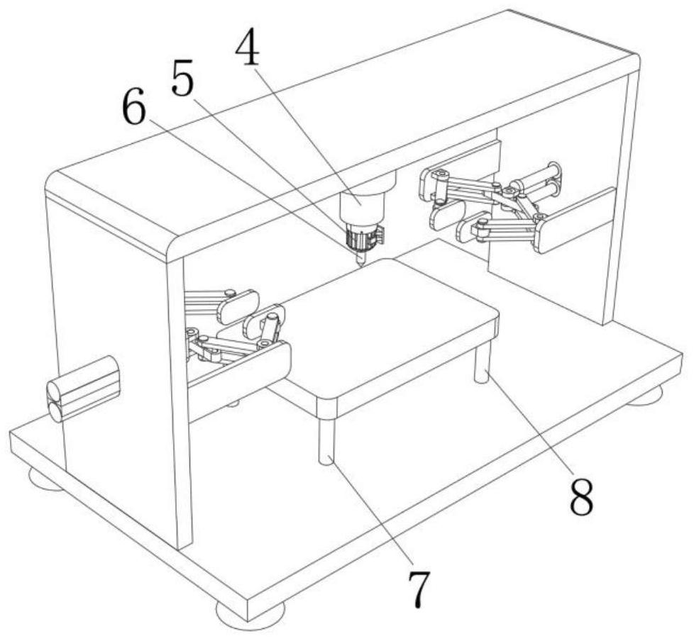
[0024] see Figure 1-3 , the present invention provides a technical solution: a clamping device for forklift parts processing, including a fixed base plate 1, the four corners of the lower surface of the fixed base plate 1 are fixedly connected with a fixed base 2, and the upper surface of the fixed base plate 1 is fixedly connected There is a gantry 3, the top inner wall of the gantry 3 is fixedly connected with a first electric push rod 4, the specific model of the first electric push rod 4 is LAP22, the output end of the first electric push rod 4 is fixedly connected with a drilling motor 5, and the drill The specific model of the hole motor 5 is 130BYG350, the output end of the drilling motor 5 is fixedly connected with a drill bit 6, the upper surface of the fixed bottom plate 1 is fixedly connected with a support column 7, and the upper surface of the support column 7 is fixedly connected with a placement plate 8, a gantry 3 The inner walls of the left and right sides ar...

Embodiment 2

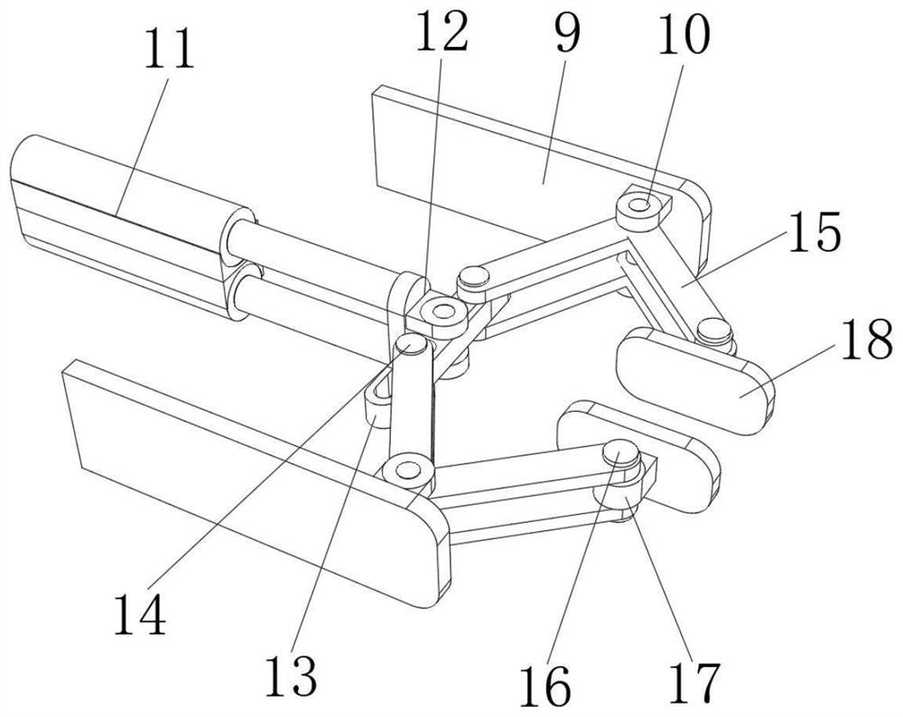
[0033] see Figure 1-2 and Figure 4 , the present invention provides a technical solution: a clamping device for forklift parts processing, including a fixed base plate 1, the four corners of the lower surface of the fixed base plate 1 are fixedly connected with a fixed base 2, and the upper surface of the fixed base plate 1 is fixedly connected There is a gantry 3, the top inner wall of the gantry 3 is fixedly connected with a first electric push rod 4, the specific model of the first electric push rod 4 is LAP22, the output end of the first electric push rod 4 is fixedly connected with a drilling motor 5, and the drill The specific model of the hole motor 5 is 130BYG350, the output end of the drilling motor 5 is fixedly connected with a drill bit 6, the upper surface of the fixed base plate 1 is fixedly connected with a support column 7, and the upper surface of the support column 7 is fixedly connected with a placement plate 8.

[0034] In the present invention, in order ...


PUM


Abstract

The invention relates to the technical field of accessory machining clamping devices, and discloses a clamping device for forklift accessory machining. The clamping device comprises a fixing bottom plate, fixing bases are fixedly connected to the four corners of the lower surface of the fixing bottom plate, a portal frame is fixedly connected to the upper surface of the fixing bottom plate, the inner wall of the top of the portal frame is fixedly connected with a first electric push rod, and the output end of the first electric push rod is fixedly connected with a drilling motor. According tothe clamping device for forklift accessory machining, a second electric push rod drives a clamping linkage rod and a clamping plate to clamp and fix an accessory, a better clamping and fixing effect is achieved on the accessory in a special shape, a better clamping effect is achieved, meanwhile, the clamping force on the accessory can be better controlled, the situation that the accessory is damaged due to too large clamping force is effectively avoided, the accessory in a special shape can be clamped more stably, and the accessory can be better machined.

Description

technical field [0001] The invention relates to the technical field of clamping devices for processing accessories, in particular to a clamping device for processing forklift parts. Background technique [0002] Accessories refer to the machine parts or parts made of them, as well as some small hardware products, which can be used alone or as auxiliary appliances, such as tools, parts, daily hardware, construction and security products, etc. Most of the small hardware products are not final consumer goods. Instead, as ancillary products, semi-finished products and tools used in the production process of industrial manufacturing, hardware accessories need to be polished on their outer surfaces during processing, and clamping devices need to be used to fix them during the grinding process; now Nowadays, most of the clamping devices often think that the pressure generated during the fixation cannot be controlled in the process of clamping the hardware accessories, which makes t...

Claims


Application Information

Patent Timeline
IPC IPC(8): B23B47/00B23Q3/06
CPCB23B47/00B23Q3/06B23Q3/062
Inventor 李强峰邱勇春李鑫曾武
Owner 湖南川田机械制造有限公司
Learn More