
Rolling type drawing device

A drawing device and rolling-type technology, which is applied in the field of rolling-type drawing devices, can solve the problems of increased wire breakage rate, scratched part cracks, scratches, etc., to reduce wire rod cracks and reduce pull Effect of wire breakage rate

Inactive Publication Date: 2021-01-15
五矿联众(天津)焊接材料有限公司
View PDF1 Cites 0 Cited by
  • Summary
  • Abstract
  • Description
  • Claims
  • Application Information

AI Technical Summary

Problems solved by technology

[0004] In the above technical solution, the wire rod can be cold-drawn by the drawing device, but scratches are easy to occur on the surface of the wire rod during the stretching process of the wire rod. During the first drawing process, as the surface of the wire rod hardens, cracks or parallel transverse cracks appear on the scratched part, which leads to an increase in the rate of broken wires in the subsequent drawing and affects the normal drawing process of the wire rod.

Method used


Image

  • Rolling type drawing device
  • Rolling type drawing device
  • Rolling type drawing device

Examples


Embodiment Construction

[0032] The following will clearly and completely describe the technical solutions in the embodiments of the present invention with reference to the drawings in the embodiments of the present invention.

[0033] In describing the present invention, it is to be understood that the terms "central", "longitudinal", "transverse", "front", "rear", "left", "right", "vertical", "horizontal", The orientations or positional relationships indicated by "top", "bottom", "inner", "outer", etc. are based on the orientations or positional relationships shown in the drawings, and are only for the convenience of describing the present invention and simplifying the description, rather than indicating or implying the The device or element referred to must have a specific orientation, be constructed and operated in a specific orientation, and therefore cannot be construed as limiting the scope of protection of the present invention. In addition, the terms "first" and "second" are only used for desc...


PUM


Abstract

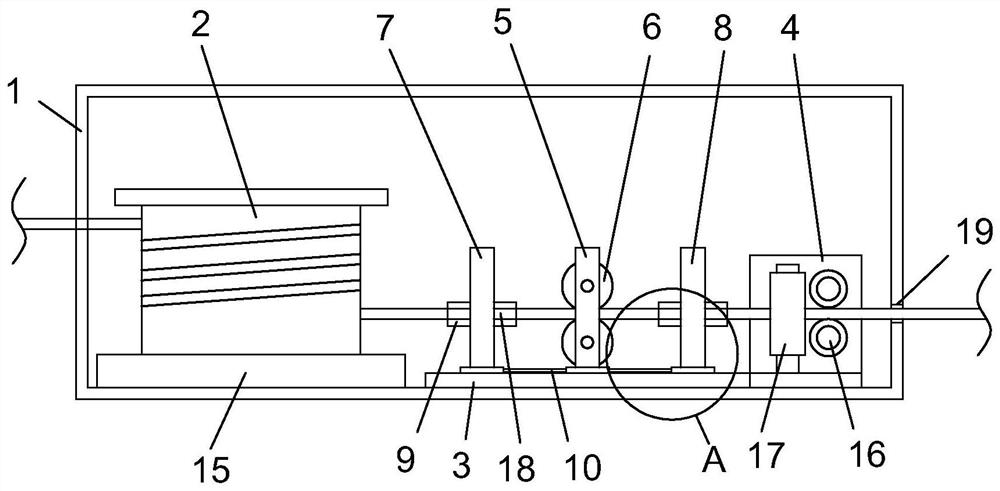
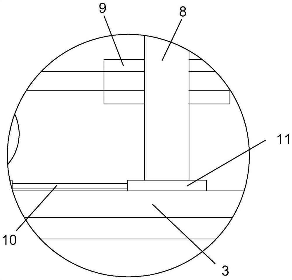
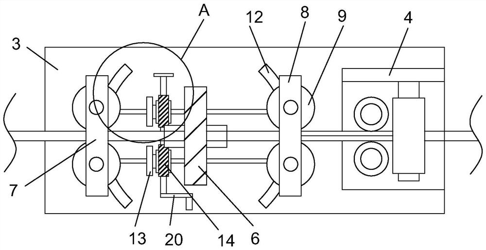
The invention discloses a rolling type drawing device. The rolling type drawing device comprises a single-rotation drawing box and a winding frame, wherein the winding frame is rotationally arranged in the single-rotation drawing box, a single-rotation drawing mechanism is arranged on the side edge of the winding frame, the single-rotation drawing mechanism comprises a soft material drawing plate,a fixed-point roller frame, a first horizontal pressing roller and a second horizontal pressing roller are arranged on the upper part of the soft material drawing plate, the fixed-point roller frameis located between the first horizontal pressing roller and the second horizontal pressing roller, two vertical pressing rollers which are arranged up and down are rotationally connected in the fixed-point roller frame, and the fixed-point roller frame is fixedly arranged on the soft material drawing plate. According to the rolling type drawing device, an offset assembly on the soft material drawing plate is used for adjusting the sliding of the first horizontal pressing roller and the second horizontal pressing roller, so that small-amplitude bending and stretching are carried out in the process that the first horizontal pressing roller and the second horizontal pressing roller drive a disc to be drawn, then the occurrence of wire rod cracks caused by surface scratches is reduced, and thewire rod drawing and breaking rate is reduced.

Description

technical field [0001] The invention relates to the technical field of welding core production equipment, in particular to a rolling-type drawing device. Background technique [0002] Welding rod refers to the metal strip that melts and fills the joint of the welding workpiece during gas welding or electric welding. It consists of two parts: the coating and the welding core. The special steel wire used for welding can be divided into three categories: carbon structural steel, alloy structural steel, and stainless steel. , The electrode coating is made of oxides, carbonates, silicates, organics, fluorides, ferroalloys and other chemical powders, etc., mixed according to a certain formula ratio. After the mixing is completed, it is pressure-coated on the welding core, and the welding core Parts are generally steel wire rods processed by drawing techniques. [0003] Patent Publication No. CN207430911U discloses a wire rod cold drawing device, the outer ring of the driving drum...

Claims


Application Information

Patent Timeline
Patent Type & Authority Applications(China)
IPC IPC(8): B21C1/16B21C1/32B21C1/30
CPCB21C1/16B21C1/30B21C1/32
Inventor 刘慧
Owner 五矿联众(天津)焊接材料有限公司
Learn More