A dispensing device for battery processing and its working method

A technology of dispensing device and battery, which is applied to devices and coatings that apply liquid to the surface, can solve the problems of dripping glue, unstable temperature, high energy consumption, etc., achieve stable dispensing, prevent waste of energy, The effect of preventing glue from solidifying

Active Publication Date: 2021-09-28
ANHUI NARADA RENEWABLE RESOURCE TECH CO LTD
View PDF26 Cites 0 Cited by
  • Summary
  • Abstract
  • Description
  • Claims
  • Application Information

AI Technical Summary

Problems solved by technology

[0005] Aiming at the deficiencies of the prior art, the present invention provides a glue dispensing device for battery processing and its working method, which has the advantages of high glue dispensing efficiency, less energy consumption, stable glue dispensing, etc. The glue efficiency is low, and some devices that rely on temperature to maintain the glue in a melted state have the problem of high energy consumption caused by temperature instability, and the glue will drip and cause unstable dispensing.

Method used


Image

  • A dispensing device for battery processing and its working method
  • A dispensing device for battery processing and its working method
  • A dispensing device for battery processing and its working method

Examples


Embodiment 1

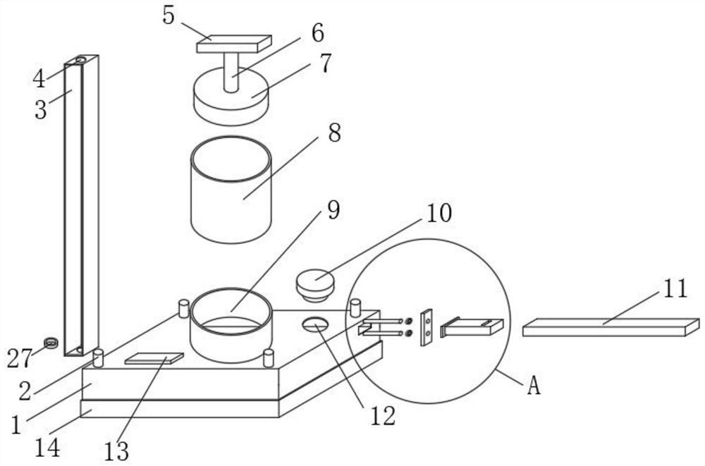
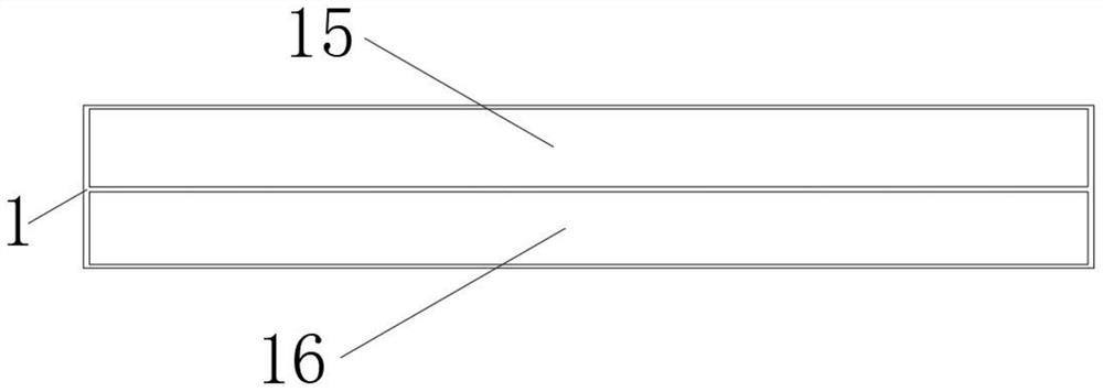
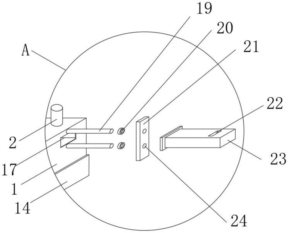
[0032] In a typical implementation of the present application, such as Figure 1-6 As shown, a dispensing device for battery processing includes a dispensing box 1, the dispensing box 1 is a rectangular structure, the inside of the dispensing box 1 is composed of a glue chamber 15 and a mold 16, and the glue chamber 15 is hollow Rectangular structure, the interior of the glue chamber 15 is provided with a heating net 25, the side wall of the glue chamber 15 is fixedly installed with a temperature sensor 26, and the middle part of the top surface of the dispensing box 1 is fixedly installed with a connecting column 9, and the connecting column 9 is open at both ends The cylindrical structure, the top surface of the dispensing box 1 covered by the bottom surface of the connecting column 9 is open, the inner wall of the connecting column 9 is provided with internal threads, and the connecting column 9 is provided with a cylinder 8, which is open at both ends. Cylindrical structur...

Embodiment 2

[0040] In order to overcome the deficiencies in the prior art, the present invention also provides a working method of a dispensing device for battery processing, the specific steps are as follows:

[0041] S1: Fill the required glue into the glue chamber 15 through the glue inlet 12, monitor the temperature through the temperature sensor 26, adjust the heating net 25, and observe the value on the display 13, so that the temperature in the glue chamber 15 is kept above the melting point of the glue to prevent The glue sets, but it should not be too high to prevent wasting energy.

[0042] S2: Monitor the pressure through the baroreceptor 18, which can be observed through the display 13, and the pressure value and temperature value will also be transmitted to the computer. The computer controls the machine and the power supply to adjust the pressure and temperature, and ensures the pressure and temperature as much as possible. Constant, and just the pressure so that the glue do...


PUM


Abstract

The invention relates to the field of battery dispensing, and discloses a dispensing device for battery processing and a working method thereof. There is a heating net, a temperature sensor is fixedly installed on one side wall of the glue chamber, a connecting column is fixedly installed in the middle of the top surface of the dispensing box, a cylinder is arranged in the connecting column, a piston is arranged in the cylinder, and a pressure sensor is arranged on the bottom surface of the piston , through the position identification frame to judge whether the battery corresponds to the mold, and the dispensing device sinks to make the mold and the surface of the battery need to be glued together, and then press the piston down by mechanical force, so that the liquid in the cylinder When the pressure rises, the glue in the glue chamber is squeezed to the required dispensing position through the mold. If the battery does not correspond to the mold, the mold will not sink. Through the above, the battery can be dispensed in batches efficiently.

Description

technical field [0001] The invention relates to the field of battery dispensing, in particular to a dispensing device for battery processing and a working method thereof. Background technique [0002] The battery is a device that converts chemical energy into electrical energy. The sealing of the battery is very important for the use of the battery. The sealing of the battery usually adopts dispensing technology, so an excellent dispensing device is very important in the processing of the battery. . [0003] Most of the dispensing devices for battery processing in the prior art are low in dispensing efficiency due to the large number of dispensing positions, and some devices that rely on temperature to maintain the melted glue consume a lot of energy due to unstable temperature. And the glue will drip and cause the problem of unstable dispensing. Contents of the invention [0004] (1) Solved technical problems [0005] Aiming at the deficiencies of the prior art, the pr...

Claims


Application Information

Patent Timeline
Patent Type & Authority Patents(China)
IPC IPC(8): B05C5/02B05C11/10B05D1/26
CPCB05C5/0208B05C11/1013B05C11/1015B05C11/1042B05D1/265
Inventor 吕明尹从友陈华勇胡磊任永刚
Owner ANHUI NARADA RENEWABLE RESOURCE TECH CO LTD
Why Eureka
Try Eureka