Airborne sprayer structure of agricultural plant protection unmanned aerial vehicle, spraying system and unmanned aerial vehicle
A plant protection drone and sprinkler technology, applied in the mechanical field, can solve problems such as complex operation, long exhaust process time, insufficient exhaust capacity of the water pump to push the pressure maintaining valve, etc., to eliminate inconvenience and solve the problem of manual exhaust Problems, realize the effect of automatic exhaust and spraying
- Summary
- Abstract
- Description
- Claims
- Application Information
AI Technical Summary
Problems solved by technology
Method used
Image
Examples
Embodiment 1
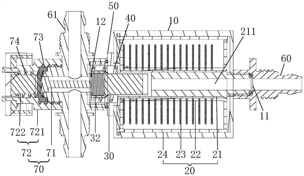
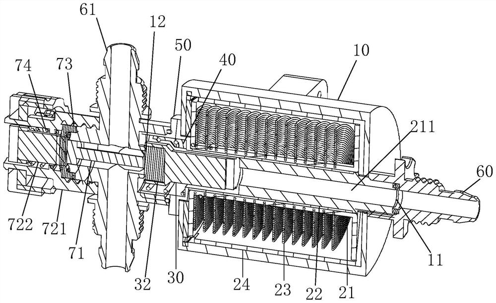
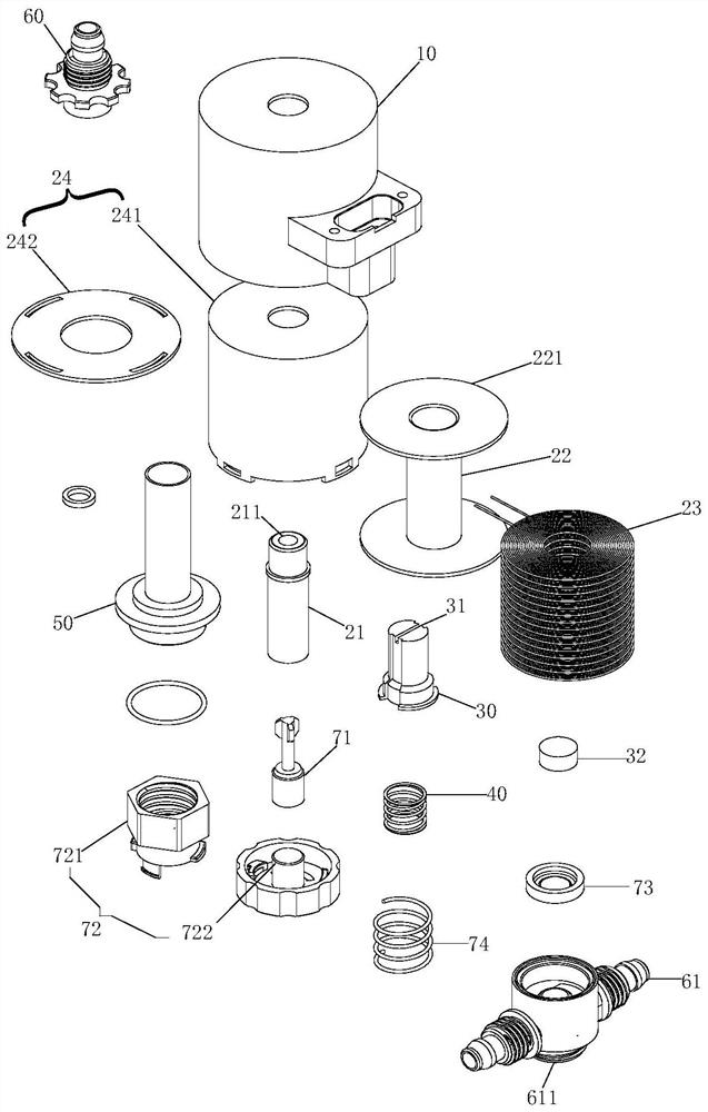
[0062] figure 1 It is a schematic cross-sectional structure diagram of an airborne nozzle structure provided by an embodiment of the present invention, figure 2 It is a three-dimensional schematic diagram of the cross-sectional structure of the airborne nozzle structure provided by an embodiment of the present invention, image 3 A schematic diagram of the exploded structure of the airborne nozzle structure provided by an embodiment of the present invention, combined with Figures 1 to 3 shown in .
[0063] In one embodiment of the present invention, an airborne spray head structure of an agricultural plant protection drone is provided, including: a valve body 10 , an electromagnet 20 and a moving part 30 .
[0064] Wherein, the valve body 10 has an inlet 11 and an outlet 12 . The electromagnet 20 is arranged in the valve body 10 , and the electromagnet 20 includes a static iron core 21 , and a first channel 211 communicating with the inlet 11 is provided on the static iro...
Embodiment 2
[0081] On the basis of embodiment 1, continue to refer to Figures 1 to 3 , a possible implementation of the electromagnet 20 is that the electromagnet 20 includes, in addition to the static iron core 21 , a bobbin 22 , a coil 23 and a yoke shell 24 . Wherein, the bobbin 22 provides support for the coil 23 . The yoke shell 24 can prevent the magnetic field generated by the coil 23 from being energized and affect other components, and also prevent external components with a magnetic field from affecting the coil 23 and the static iron core 21 . Specifically, the implementation of the coil bobbin 22, the coil 23 and the yoke shell 24 includes that the coil bobbin 22 has a through-type inner cavity, the static iron core 21 is sleeved in the inner cavity of the coil bobbin 22, and the coil 23 is wound on the coil bobbin. 22 outer surface, the yoke shell 24 wraps the outer surface of the coil 23, and the yoke shell 24 is provided with a through hole communicating with the passage....
Embodiment 3
[0086] On the basis of embodiment 2, continue to refer to Figures 1 to 3 , The yoke shell 24 includes: a first yoke 241 and a second yoke 242 . The first yoke 241 and the second yoke 242 form the yoke shell 24 to protect the inner coil 23 , the static iron core 21 and the coil bobbin 22 . A specific implementation of the first yoke 241 and the second yoke 242 is that the first yoke 241 has a mounting cavity, the bobbin 22 and the coil 23 are disposed in the mounting cavity, and a through hole is disposed at the bottom of the mounting cavity. The second yoke 242 is connected to the first yoke 241 and covers the installation cavity, and a through hole is disposed on the second yoke 242 .
[0087]When installing, the coil 23, the static iron core 21 and the bobbin 22 can be formed into a whole, and then they are installed in the first yoke 241 as a whole, and then the second yoke 242 is installed on the first yoke 241. , the installation cavity of the first yoke 241 is covered...
PUM
 Abstract
Description
Claims
Application Information
 - R&D Engineer
- R&D Manager
- IP Professional
- Industry Leading Data Capabilities
- Powerful AI technology
- Patent DNA Extraction
Browse by: Latest US Patents, China's latest patents, Technical Efficacy Thesaurus, Application Domain, Technology Topic, Popular Technical Reports.
© 2024 PatSnap. All rights reserved.Legal|Privacy policy|Modern Slavery Act Transparency Statement|Sitemap|About US| Contact US: help@patsnap.com


