Phase-control multichannel sound wave directional emission method and system
A directional emission, multi-channel technology, applied in ultrasonic/sonic/infrasonic transmission systems, transmission systems, sound-generating devices, etc., can solve problems such as inability to realize multi-channel and inability to transmit ultrasonic waves
- Summary
- Abstract
- Description
- Claims
- Application Information
AI Technical Summary
Problems solved by technology
Method used
Image
Examples
Embodiment 1
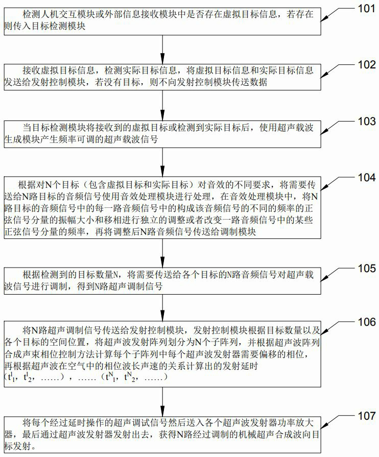
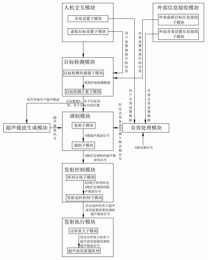
[0088] Example 1. As attached to the manual Figure 12 shown. A set of phase-controlled multi-channel sound wave directional emission system is placed on the desktop. The cylindrical object 201 in the figure is the target detection module; the default emission mode of the system is focus mode; the system detects whether there is a virtual target in the human-computer interaction module or the external information receiving module Information, in this embodiment, there is no virtual target information; the system detects that there are 4 targets around through the target detection module, which are respectively the left ear and the right ear of user A, and the left ear and right ear of user B. The left and right ears of user A transmit the left channel audio and right channel audio of audio A that user A needs to hear, and transmit the left channel of audio B that user B needs to hear to the left and right ears of user B Audio and right channel audio, and user A and user B ca...
Embodiment 2
[0089] Embodiment 2, as specification attached Figure 13shown. In the desktop environment, the left and right channel audio is transmitted to the left and right ears of the user through the ultrasonic array, which can prevent the audio that the user needs to hear from spreading to the surrounding space, causing privacy leakage and causing noise to other users. Laptops, tablet computers, and mobile phones are placed in sequence on the same desktop. The laptops, tablet computers, and mobile phones each have a set of phase-controlled multi-channel sound wave directional emission systems, and there is a user for each of these three devices. In the phase-controlled multi-channel sound wave directional emission system of the notebook computer, 301 is the target detection sensor sub-module deployed in the target detection module of the notebook computer, and its coordinate system is X1-Y1-Z1, and the sub-tables 302 and 303 are deployed The ultrasonic sub-array between the keyboard ...
Embodiment 3
[0090] Embodiment 3, as specification attached Figure 14 shown. In the multi-person large space scene, a set of phased multi-channel sound wave directional emission system is installed in the top space. The cylindrical shape 401 in the figure represents the target detection sensor sub-module of the system, and other modules are integrated into the ultrasonic emission sub-array. , 402, 403, 404, 405, 406, and 407 are ultrasonic transmitting sub-arrays integrated with power amplifiers respectively, and 402~407 together constitute a transmitting execution module. Assuming that there are 3 users, after the phased multi-channel sound wave directional emission system is started, the default emission mode is in focus mode; the 3 users can use the human-computer interaction module to set their own sound effects; the system first detects the human-computer interaction module or external information Whether there is virtual target information in the receiving module, in this embodimen...
PUM
 Abstract
Description
Claims
Application Information
 - Generate Ideas
- Intellectual Property
- Life Sciences
- Materials
- Tech Scout
- Unparalleled Data Quality
- Higher Quality Content
- 60% Fewer Hallucinations
Browse by: Latest US Patents, China's latest patents, Technical Efficacy Thesaurus, Application Domain, Technology Topic, Popular Technical Reports.
© 2025 PatSnap. All rights reserved.Legal|Privacy policy|Modern Slavery Act Transparency Statement|Sitemap|About US| Contact US: help@patsnap.com


