
Heating cooking utensil

A heater and cooker technology, which is applied to electric heating fuel, lighting and heating equipment, electric/magnetic/electromagnetic heating, etc., can solve the problems of inability to cook a large number of heated objects, dark roasting, and time-consuming heating. The effect of inhibiting the drying of the food surface and the uneven grilling, the good finished product state, and the reduction of heat release

Inactive Publication Date: 2003-09-24
PANASONIC CORP
View PDF0 Cites 0 Cited by
  • Summary
  • Abstract
  • Description
  • Claims
  • Application Information

AI Technical Summary

Problems solved by technology

In addition, the hot air directly contacts the surface of the heated object 1, so the water layer on the surface of the heated object 1 is evaporated, and only the surface is rapidly heated and dried, which is regarded as the cooking completion state. Sufficient heating does not give good cooking results
Therefore, in the prior art, efforts have been made to improve the cooking result by adjusting the hot air blowing position and air volume, but there are many difficulties and are not satisfactory.
[0008] And, on the other hand, in the conventional convection heating method that adopts the top plate heater and the bottom plate heater, the number of places to use is limited, and a large amount of objects to be heated cannot be cooked at one time. If the amount of cooking is to be increased, the heating chamber must In this case, the heating time must be consumed and the power consumption of the heater will be increased.
[0009] Therefore, there are also heating cookers with both convection and hot air circulation methods, but they cannot fully make up for their respective defects, especially when cooking with two layers, uneven grilling and dryness occur, and the cooking effect is not good.
[0010] In addition, in cooking such as grilled meat and fish, the surface of the object to be heated is scorched in a short time, because only the top plate heater is used for cooking, the cooking object must be turned during cooking, and the cooking situation must be paid attention to, so it is troublesome.

Method used


Image

  • Heating cooking utensil
  • Heating cooking utensil
  • Heating cooking utensil

Examples


Embodiment Construction

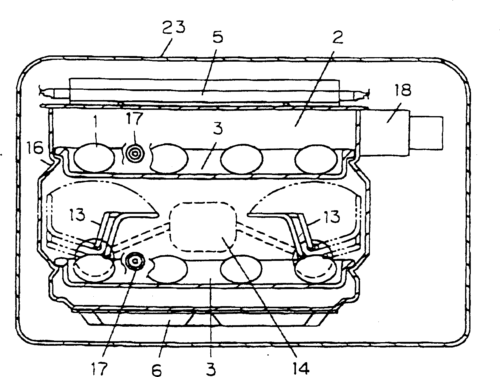
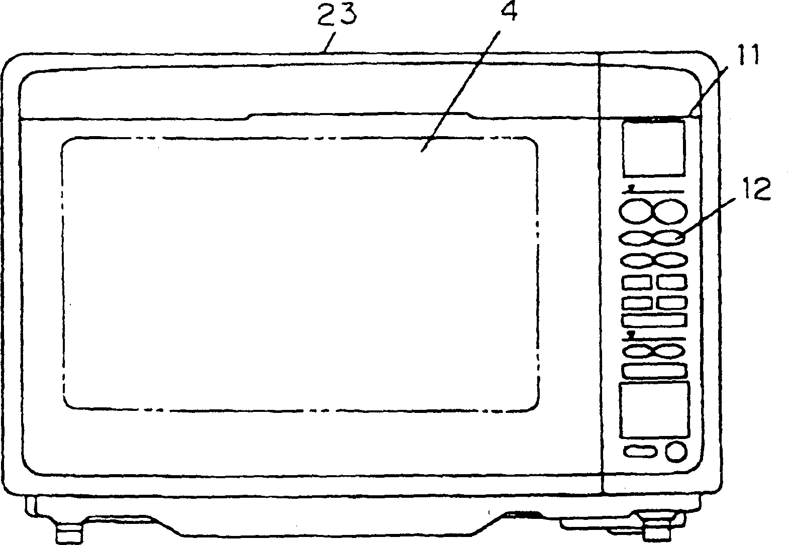
[0032] Hereinafter, an embodiment of the present invention will be described with reference to the accompanying drawings, and components with the same names as those in the prior art embodiment will be given the same reference numerals and their descriptions will be omitted.

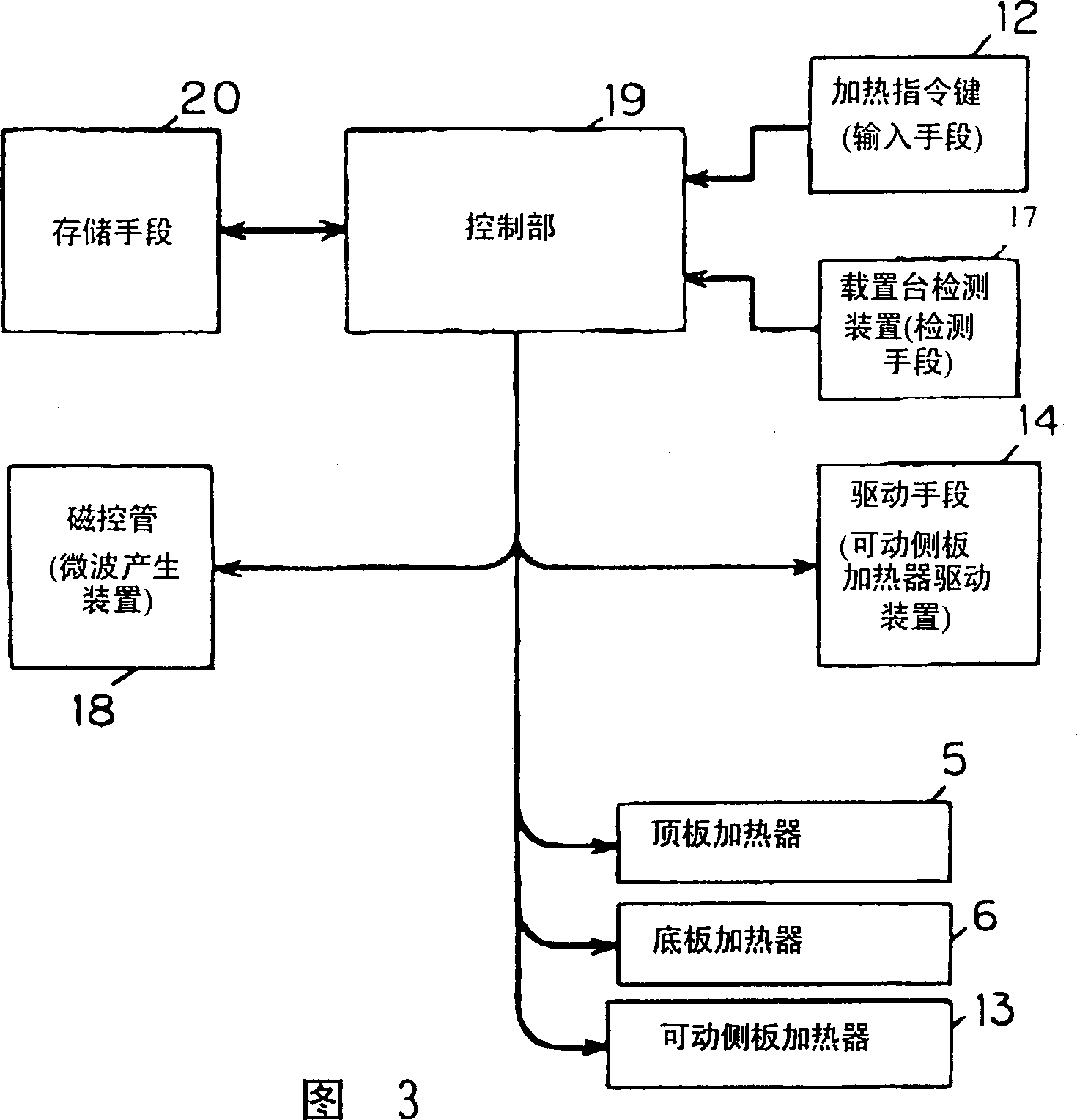
[0033] figure 2 It is an external view of the heating cooker according to the food heating method of the present invention. That is, the door 4 is pivotally supported on the front surface of the furnace body 23 so as to be openable and closable, and closes the opening of the heating chamber for accommodating food. A heating command key 12 as an input device is arranged on the operation panel 11, and a heating method is selected based on a code input through the heating command key 12 and information from a stage detection device described later, and a command is issued to the control unit.

[0034] figure 1 It is a front sectional view of the heating chamber. In the heating chamber 2, a top plate he...


PUM


Abstract

PROBLEM TO BE SOLVED: To effect a heat cooking preferably by controlling a side plate heater which can be moved in response to a size or an amount of item to be heated. SOLUTION: This heat cooking device is provided with a heating chamber 2 for storing a product 1 to be heated, a mounting table 3 for mounting the product 1 to be heated, a ceiling plate heater 5 for use in heating the product 1 to be heated, a bottom plate heater 6, a movable side plate heater 13, a driving means 14 for driving the movable side plate heater 13, and a control section for supplying a power source to each of the heaters and for controlling the driving means 14. The movable side plate heater 13 is controlled by the driving means 14 in reference to the cooking menu and the heater is moved while being rotated or being rotated and ascended or descended as well. With such an arrangement as above, it is possible to perform a superior heating and cooking of various kinds of products to be heated while irregular cooked part or excessive drying as found in the conventional heating system of hot air circulation can be restricted.

Description

technical field [0001] The invention relates to a heating cooker such as a grill microwave oven which uses a radiation heater and a microwave generator as heating devices to cook a variety of foods with an optimum heating method. Background technique [0002] As can be seen from previous grilling microwave ovens, the heating methods using heaters include: the so-called convection method in which heaters are arranged on the top and bottom plates of the heating chamber, and the radiant heat and convective heat of the heaters are used for heating and cooking; The so-called hot air circulation method in which the heat is sent into the heating chamber and the hot air is used for heating and cooking. [0003] Hereinafter, the configuration of the hot air circulation system as an example will be described with reference to the drawings. [0004] Such as Figure 7 As shown, the furnace of this mode consists of a heating chamber 2 for heating the object to be heated 1, a mounting pl...

Claims


Application Information

Patent Timeline
Patent Type & Authority Patents(China)
IPC IPC(8): H05B11/00F24C7/02F24C7/06
CPCH05B6/6447H05B6/6485H05B6/664
Inventor 児玉智朝比奈孝
Owner PANASONIC CORP
Learn More