
Fluid flow velocity sensor and system based on surface acoustic waves

A technology of fluid flow velocity and surface acoustic wave, applied in the field of fluid sensing, can solve the problems of large buoy volume, measurement error and low sensitivity of the fluid to be measured

Inactive Publication Date: 2021-01-12
金华伏安光电科技有限公司
View PDF0 Cites 0 Cited by
  • Summary
  • Abstract
  • Description
  • Claims
  • Application Information

AI Technical Summary

Problems solved by technology

[0005] The purpose of the present invention is to provide a surface acoustic wave fluid flow velocity sensor and system to solve the problems in the prior art that the volume of the buoy is large and the corresponding resistance is relatively large, so that the fluid to be measured There is a certain error in the measurement of the measured fluid, which makes the problem of low sensitivity and low precision in measuring the flow rate of the fluid to be measured

Method used


Image

  • Fluid flow velocity sensor and system based on surface acoustic waves
  • Fluid flow velocity sensor and system based on surface acoustic waves
  • Fluid flow velocity sensor and system based on surface acoustic waves

Examples


Embodiment 1

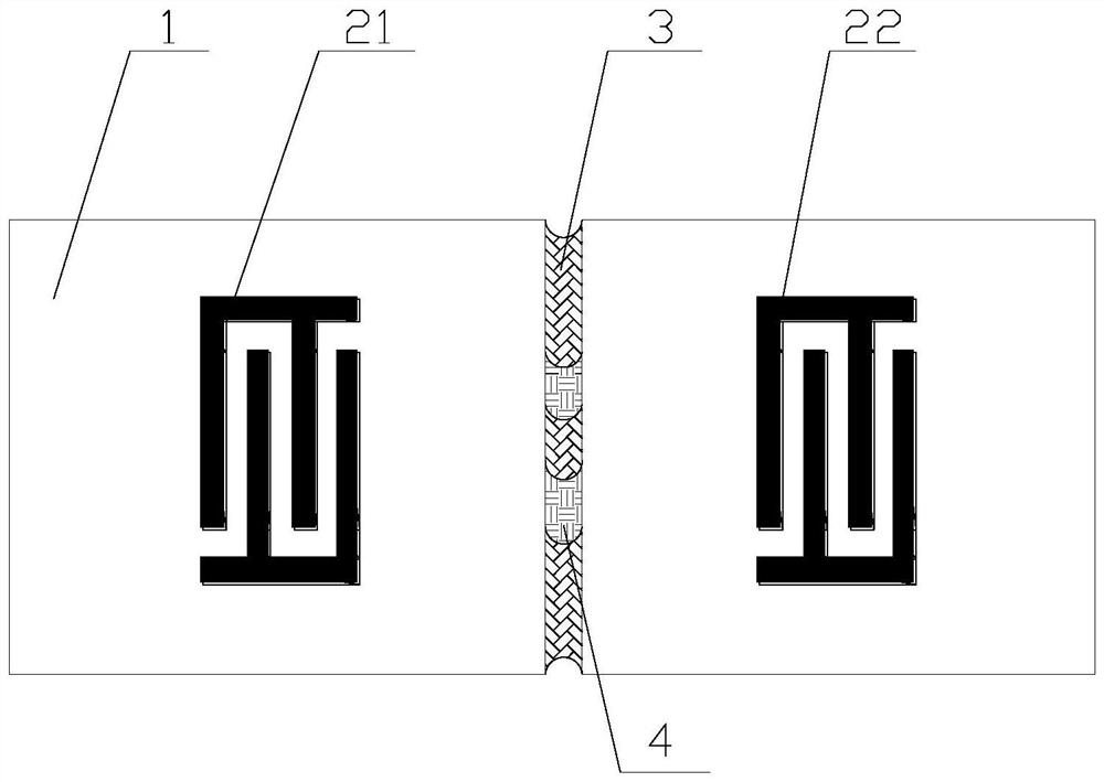
[0031] The present invention provides a fluid velocity sensor based on surface acoustic waves. The fluid velocity sensor comprises: a base 1, a first electrode 21, and a second electrode 22; There is a fluid channel 3, a section of the inner wall of the fluid channel 3 is provided with an adhesive layer 4, and the first electrode 21 and the second electrode 22 are respectively arranged on both sides of the fluid channel 3; the material of the first electrode 21 and the second electrode 22 is conductive Metal material, the material of the adhesive layer 4 is a fluid adhesive material, and the material of the substrate 1 is a piezoelectric material.

[0032]The shape of the base 1 can be a cube, it can be a cuboid, and it can also be a truss. There is a fluid channel 3. The cross-sectional area and shape of the fluid channel 3 are set according to actual needs, and are not specifically limited here. The two sides of the fluid channel 3 are respectively provided with a first elec...

Embodiment 2

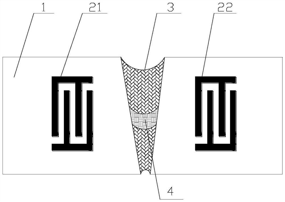
[0047] Based on Embodiment 1, this embodiment of the present application provides another surface acoustic wave-based fluid velocity sensor. It is basically the same as Embodiment 1, the only difference is that the thickness of the fluid channel 3 of the fluid velocity sensor is decreasing.

[0048] After the fluid to be tested passes through the fluid channel 3 , it will be adhered to the adhesive layer 4 . The amount of adhesion is related to the fluid flow rate. When the first electrode 21 applies an excitation signal, a surface acoustic wave will be generated on the surface of the substrate 1, and the surface acoustic wave passes through the fluid channel 3 during propagation, and is affected by the adhesive fluid of the adhesive layer 4, so that the dielectric constant of the substrate 1 A corresponding change occurs, resulting in a corresponding change in the frequency of the surface acoustic wave. Since the flow velocity of the fluid corresponds to the frequency of th...

Embodiment 3

[0050] figure 2 Another surface acoustic wave-based fluid flow velocity sensor provided by an embodiment of the present invention is based on embodiment 2, and this application embodiment provides another surface acoustic wave-based fluid flow velocity sensor. It is basically the same as Embodiment 2, except that there are multiple adhesive layers 4 in the fluid channel 3 of the fluid flow sensor. For clarity, the number of the adhesive layers 4 is two for illustration.

[0051] Optionally, there may be multiple adhesive layers 4 in the fluid channel 3 of the fluid velocity sensor. This makes it easier to stick fluids.

[0052] After the fluid to be tested passes through the fluid channel 3 , it will be adhered to the adhesive layer 4 . The amount of adhesion is related to the fluid flow rate. When the first electrode 21 and the second electrode 22 apply an excitation signal, a surface acoustic wave will be generated on the surface of the substrate 1, and the surface acous...


PUM


Abstract

The invention relates to a fluid flow velocity sensor and system based on surface acoustic waves, in particular to the field of fluid sensing. The fluid flow velocity sensor comprises a substrate, a first electrode and a second electrode, when the flow velocity of a fluid to be measured needs to be measured, a radio frequency signal with a specific frequency is inputted to the sensor, resonance occurs at the first electrode to generate an electric signal, the electric signal is converted into an acoustic signal through the inverse piezoelectric effect due to interaction of the first electrodeand the substrate, and therefore the acoustic surface waves can be generated on the surface of the substrate. Under the action of fluid in the adhesion layer, the dielectric constant of the substrateis correspondingly changed so that the frequency of the surface acoustic waves is correspondingly changed, at the second electrode, the substrate and the second electrode interact with each other to convert an acoustic signal into an electric signal through a piezoelectric effect, and frequency detection of the changed surface acoustic waves is realized. The flow velocity of the fluid to be measured is obtained according to the corresponding relation between the flow velocity of the fluid and the frequency of the surface acoustic waves.

Description

technical field [0001] The invention relates to the field of fluid sensing, in particular to a surface acoustic wave-based fluid velocity sensor and system. Background technique [0002] Fluid is an object form corresponding to solid, and it is a general term for liquid and gas. It is composed of a large number of molecules that are constantly in thermal motion and have no fixed equilibrium position. Its basic characteristics are that it has no definite shape and has fluidity. Fluid has the same mass and density as other substances, and has certain compressibility. The compressibility of liquid is small, while the compressibility of gas is relatively large. When the shape of the fluid changes, there is also a certain gap between the layers of the fluid. Resistance to movement (i.e. viscosity). When the viscosity and compressibility of the fluid are small, it can be regarded as an ideal fluid approximately. It is an ideal model introduced by people to study the motion and s...

Claims


Application Information

Patent Timeline
Patent Type & Authority Applications(China)
IPC IPC(8): G01P5/24
CPCG01P5/24
Inventor 不公告发明人
Owner 金华伏安光电科技有限公司
Learn More