Eureka AIR delivers breakthrough ideas for toughest innovation challenges, trusted by R&D personnel around the world.

A Free Boundary Simulator for Horizontal Vibration Experiments

A simulation device and experiment technology, which is applied in the field of free boundary simulation device of horizontal vibration experiment, can solve the problems such as the inability to meet the three-way vibration reduction and isolation, and achieve the effect of improving the research level.

Active Publication Date: 2021-07-27
HARBIN ENG UNIV
View PDF0 Cites 0 Cited by
  • Summary
  • Abstract
  • Description
  • Claims
  • Application Information

AI Technical Summary

Problems solved by technology

[0003] In order to solve the problem that the existing experimental device cannot meet the actual needs of the horizontal direction vibration test experiment in the research field of three-way vibration reduction and isolation technology, the present invention further provides a free boundary simulation device for the horizontal vibration experiment;

Method used


Image

  • A Free Boundary Simulator for Horizontal Vibration Experiments
  • A Free Boundary Simulator for Horizontal Vibration Experiments
  • A Free Boundary Simulator for Horizontal Vibration Experiments

Examples


specific Embodiment approach 1

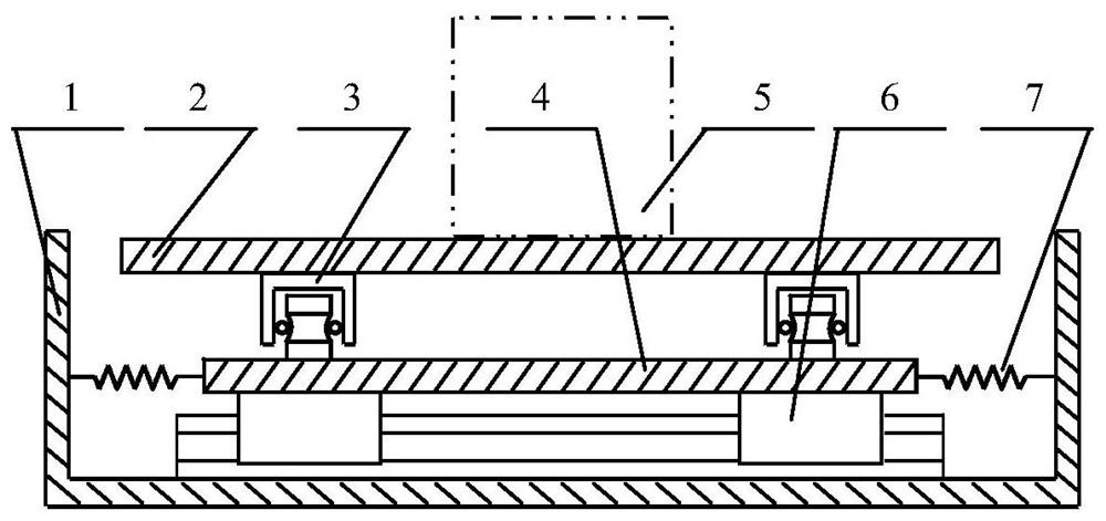
[0025] Specific implementation mode one: refer to Figure 1 to Figure 3 To illustrate this embodiment, this embodiment provides a free boundary simulation device for horizontal vibration experiments, the simulation device includes a box body 1, an upper platform assembly, a lower platform assembly, an upper level adjustment unit and a lower level adjustment unit;

[0026] The top of the box body 1 is provided with an opening, the upper platform assembly and the lower platform assembly are all arranged in the box body 1, the bottom of the lower platform assembly is fixed on the bottom plate in the box body 1, and the bottom of the upper platform assembly is fixed on the The lower platform assembly is on the platform surface, and the lower platform assembly is connected to one set of opposite inner walls of the box 1 through the lower level adjustment unit, and the upper platform assembly is connected to another set of opposite inner walls of the box 1 through the upper level adj...

specific Embodiment approach 2

[0028] Specific implementation mode two: refer to Figure 1 to Figure 3 Describe this embodiment. This embodiment is to further limit the lower platform assembly described in the first specific embodiment. In this embodiment, the lower platform assembly includes a lower platform 4 and two lower rail units 6;

[0029] The lower guide rail unit 6 includes a No. 1 guide rail and two No. 1 sliders, the two No. 1 sliders are arranged on the No. 1 guide rail, and the two No. 1 sliders are slidably connected to the No. 1 guide rail;

[0030] The two lower rail units 6 are arranged relatively parallel, and the bottom of the No. 1 rail in each lower rail unit 6 is fixedly connected to the bottom plate in the box body 1, and the lower platform 4 is arranged on the two lower rail units 6, and the lower platform The bottom of 4 is fixedly connected with each No. 1 slide block, and the lower platform 4 is connected with a group of opposite inner walls in the box body 1 through the lower le...

specific Embodiment approach 3

[0031] Specific implementation mode three: refer to Figure 1 to Figure 3 Describe this embodiment. This embodiment is to further limit the lower level adjustment unit described in the second specific embodiment. In this embodiment, the lower level adjustment unit includes two lower spring groups, and each lower spring group includes Two lower springs 7, and the axes of the two lower springs 7 are arranged in parallel, and the two lower spring groups are respectively arranged on opposite sides in the lower platform 4, and one end of each lower spring 7 is fixed to one side of the lower platform 4 The other end of each lower spring 7 is fixedly connected with the inner wall of the corresponding box body 1 . Other compositions and connection methods are the same as those in the second embodiment.


PUM


Abstract

A free boundary simulation device for a horizontal vibration experiment belongs to the technical field of mechanical vibration and noise control. In order to solve the problem that the existing experimental device cannot meet the actual needs of the horizontal direction vibration test experiment in the research field of three-way vibration damping and isolation technology, the present invention is The invention describes a free boundary simulation device for a horizontal vibration experiment, wherein the top of the box is provided with an opening, the upper platform assembly and the lower platform assembly are both arranged in the box, and the bottom of the lower platform assembly is fixed on the bottom plate in the box, The bottom of the upper platform assembly is fixed on the platform surface of the lower platform assembly, and the lower platform assembly is connected to a set of opposite inner side walls in the box through the lower leveling unit, and the upper platform assembly is connected to the other in the box through the upper leveling unit. A set of opposing inner side walls are connected. The invention provides new ideas for the research of the three-way vibration damping and isolation technology, provides effective technical support for the popularization and application of new high-precision equipment, and has important theoretical and practical significance.

Description

technical field [0001] The invention belongs to the technical field of mechanical vibration and noise control, and in particular relates to a free boundary simulation device for horizontal vibration experiments. Background technique [0002] Vibration test experiment is a necessary means for the research of mechanical vibration and noise control technology, in which the simulation and realization of the boundary conditions of the tested part have a direct impact on the experimental results. In the common vibration test experiments, there are abundant means of simulating the boundary in the vertical direction, but the development of the free boundary simulating device in the horizontal direction is relatively lagging behind. This cannot meet the requirements of the horizontal vibration test experiment, which seriously restricts the research of three-dimensional vibration reduction and isolation technology. Contents of the invention [0003] In order to solve the problem th...

Claims


Application Information

Patent Timeline
Patent Type & Authority Patents(China)
IPC IPC(8): G01M7/06
CPCG01M7/06
Inventor 温舒瑞吴志静李凤明
Owner HARBIN ENG UNIV
Why Eureka
Eureka Blog
Learn More