
Workshop ventilation system

A technology for ventilation systems and workshops, applied in ventilation systems, space heating and ventilation, space heating and ventilation details, etc., can solve problems such as failure to meet hygienic requirements, achieve improved working environment, novel design, and improved ventilation effects Effect

Pending Publication Date: 2021-01-12
贵州玄武岩新材料工程技术开发有限公司
View PDF5 Cites 1 Cited by
  • Summary
  • Abstract
  • Description
  • Claims
  • Application Information

AI Technical Summary

Problems solved by technology

[0004] In the process of processing, there is a large heat dissipation and fine powder layer in the drawing work area, and the smoke exhaust system will also generate a large heat source. The local exhaust air in the entire workshop cannot meet the hygienic requirements.

Method used


Image

  • Workshop ventilation system
  • Workshop ventilation system
  • Workshop ventilation system

Examples


Embodiment 1

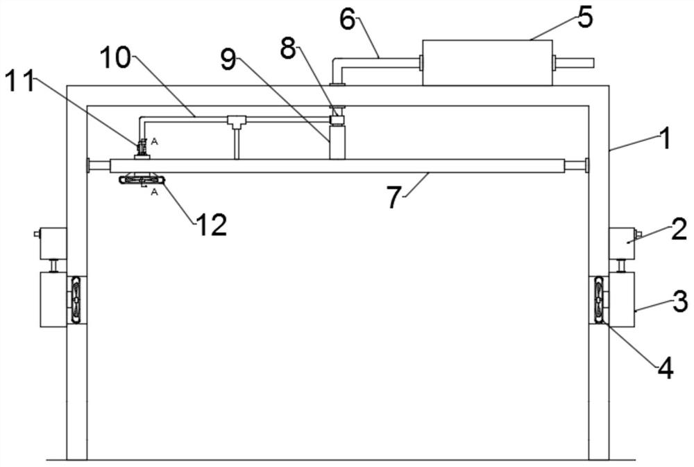
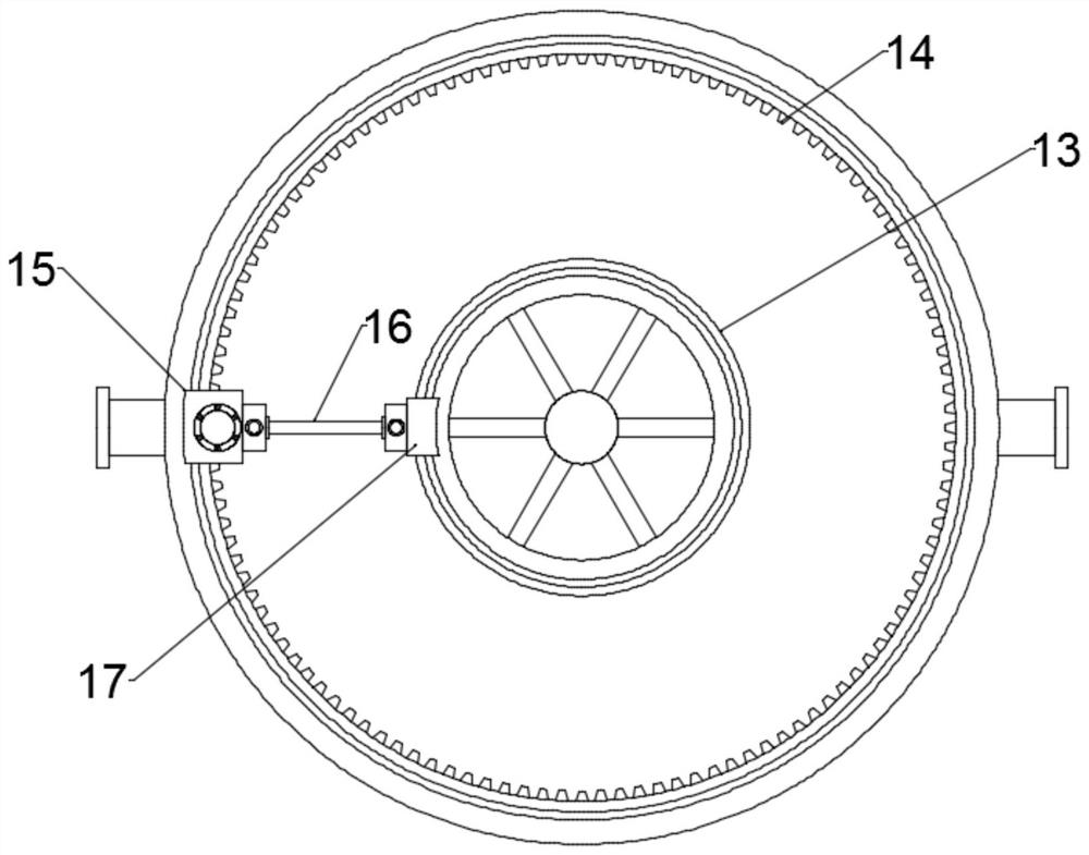
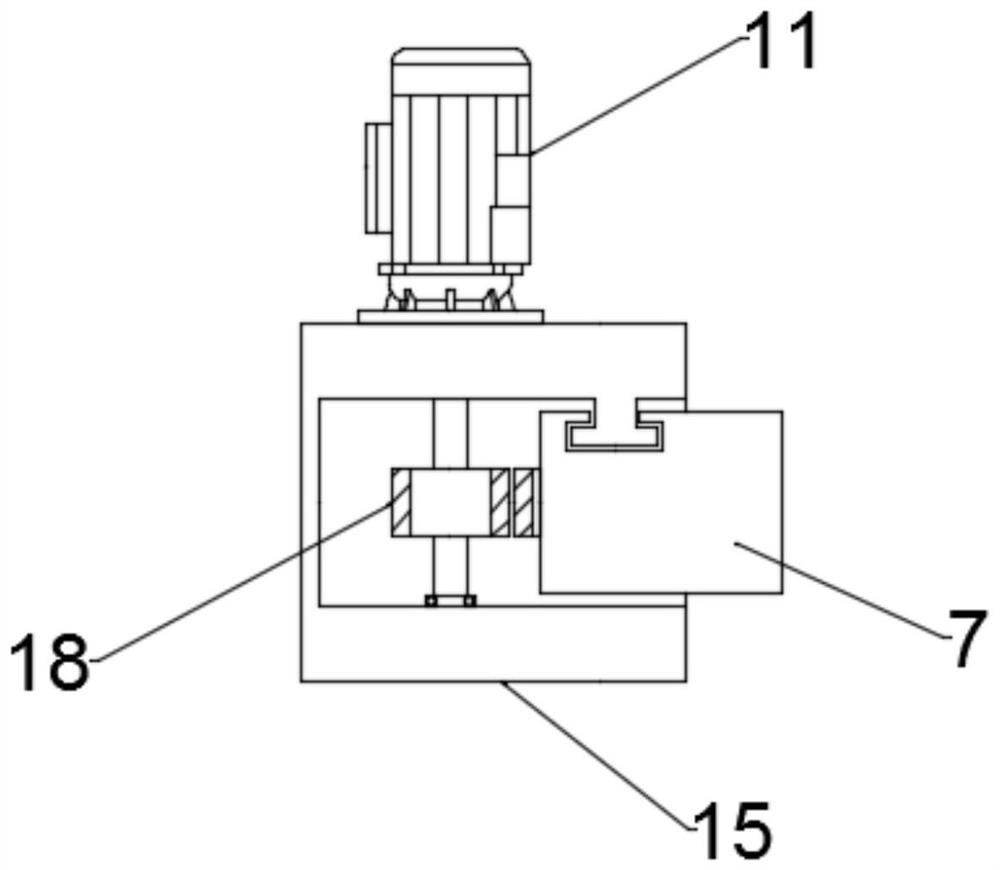
[0025] see Figure 1~4 , in an embodiment of the present invention, a ventilation system for a workshop, including at least one air intake assembly arranged at the side end of the wall body 1 and an air suction assembly arranged between the walls; two groups of the air suction assembly are provided, and Installed on the first sliding seat 15 slidingly connected with the first annular support 7 and the second sliding seat 17 slidingly connected with the second annular support 13, the first sliding seat 15 is fixedly connected with the second sliding seat 17 through the connecting rod 16 , the first sliding seat 15 is arranged in a U-shaped structure, its upper end is provided with a motor 11, the output shaft of the motor 11 is fixedly connected with the gear 18 arranged inside the first sliding seat 15, and the gear 18 is connected with the first ring bracket 7. The inner ring teeth 14 on the inner wall are meshed. When the motor 11 is working, the air suction assembly follows...

Embodiment 2

[0033] see Figure 1~4 , in an embodiment of the present invention, a ventilation system for a workshop, including at least one air intake assembly arranged at the side end of the wall body 1 and an air suction assembly arranged between the walls; two groups of the air suction assembly are provided, and Installed on the first sliding seat 15 slidingly connected with the first annular support 7 and the second sliding seat 17 slidingly connected with the second annular support 13, the first sliding seat 15 is fixedly connected with the second sliding seat 17 through the connecting rod 16 , the first sliding seat 15 is arranged in a U-shaped structure, its upper end is provided with a motor 11, the output shaft of the motor 11 is fixedly connected with the gear 18 arranged inside the first sliding seat 15, and the gear 18 is connected with the first ring bracket 7. The inner ring teeth 14 on the inner wall are meshed. When the motor 11 is working, the air suction assembly follows...


PUM


Abstract

The invention relates to the technical field related to ventilation, in particular to a workshop ventilation system. The system comprises at least one air inlet assembly arranged at the side end of each wall body and air suction assemblies arranged between the wall bodies. The two sets of air suction assemblies are installed on a first sliding base slidably connected with a first annular support and a second sliding base slidably connected with a second annular support correspondingly, the first sliding base is of a U-shaped structure, a motor is arranged at the upper end of the first slidingbase, an output shaft of the motor is fixedly connected with a gear arranged on the inner side of the first sliding base, and the gear is engaged with inner ring teeth arranged on the inner wall of the first annular support. The workshop ventilation system is novel in design, when the motor works, the positions of the air suction assemblies are changed along with the first sliding base, so that the air suction range is increased, multi-position air suction treatment in a workshop is achieved, it can be guaranteed that impurities such as fine dust in the workshop are effectively removed, the ventilation effect in the workshop is improved, and the effective working environment improving effect is achieved.

Description

technical field [0001] The invention relates to the technical field related to ventilation, in particular to a workshop ventilation system. Background technique [0002] Basalt (basalt), the main component of oceanic crust, is a basic volcanic rock. It is the most important component of the earth's oceanic crust and the moon's maria, and is also an important component of the earth's continental crust and the moon's land. [0003] Basalt fiber: continuous fiber drawn from natural basalt. It is a continuous fiber drawn at high speed by a platinum-rhodium alloy drawing bushing after melting basalt rock at 1450°C-1500°C. The color of pure natural basalt fiber is generally brown with metallic luster. Basalt fiber is a new type of inorganic environmentally friendly green high-performance fiber material, which is composed of oxides such as silicon dioxide, aluminum oxide, calcium oxide, magnesium oxide, iron oxide and titanium dioxide. Basalt continuous fiber not only has high ...

Claims


Application Information

Patent Timeline
Patent Type & Authority Applications(China)
IPC IPC(8): F24F7/013F24F13/28F24F13/32F27D17/00B08B15/00
CPCF24F7/013F24F13/28F24F13/32F27D17/008B08B15/00
Inventor 何世睿
Owner 贵州玄武岩新材料工程技术开发有限公司
Learn More