
Combined transformer

A combined transformer and transformer technology, which is applied in the field of transformer equipment, can solve problems such as difficulty, heat damage to the internal components of the transformer, and high operating risks, so as to reduce difficulty, improve installation efficiency and accuracy, and improve safety.

Inactive Publication Date: 2021-01-08
湖南领凡信息咨询有限公司
View PDF4 Cites 0 Cited by
  • Summary
  • Abstract
  • Description
  • Claims
  • Application Information

AI Technical Summary

Problems solved by technology

The disadvantages of related technologies are: on the one hand, due to the integrated structure of the transformer base and the shell, the heat during welding may damage the internal components of the transformer; The installation position is aligned with the embedded parts on the concrete base. The transformer as a whole has a heavy overall structure. It is difficult to adjust the relative position of the transformer bottom and the metal embedded parts on the concrete base, and the operation risk is high.

Method used


Image

  • Combined transformer

Examples


Embodiment Construction

[0017] The following will clearly and completely describe the technical solutions in the embodiments of the present invention with reference to the accompanying drawings in the embodiments of the present invention. Obviously, the described embodiments are only some, not all, embodiments of the present invention. Based on the embodiments of the present invention, all other embodiments obtained by persons of ordinary skill in the art without making creative efforts belong to the protection scope of the present invention.

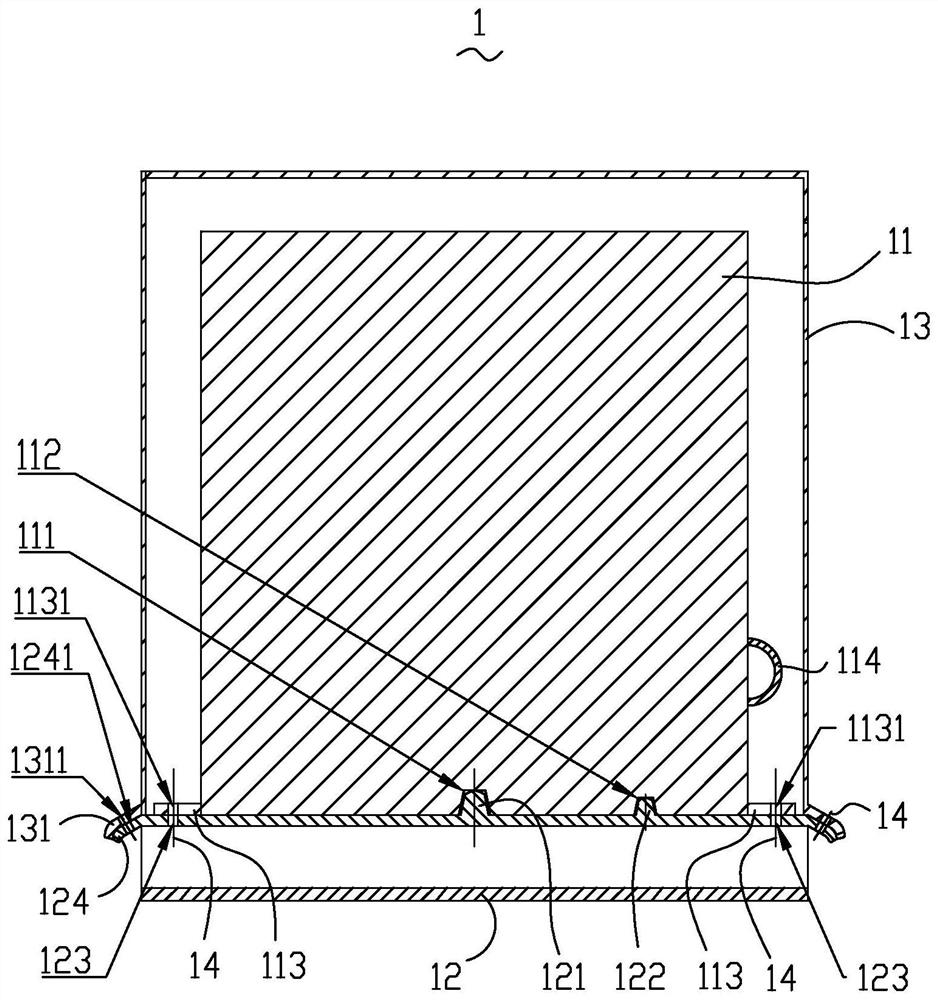
[0018] Please attach figure 1 , a combined transformer 1, comprising a transformer main body 11, a transformer base 12, and a transformer housing 13; the upper part of the transformer base 12 is provided with a raised first positioning pile 121, and the lower part of the transformer main body 11 corresponds to the first The position of a positioning pile 121 is provided with a first positioning groove 111 formed by depression, and the first positioning pile 12...


PUM


Abstract

The invention belongs to the field of voltage transformation equipment, and particularly discloses a combined transformer, which comprises a transformer main body, a transformer base and a transformershell, wherein a protruding first positioning pile is arranged on the upper portion of the transformer base, a first positioning groove formed by sinking is formed in the position, corresponding to the first positioning pile, of the lower portion of the transformer main body, the first positioning pile extends into the first positioning groove, a protruding second positioning pile is further arranged on the upper portion of the transformer base, a sunken second positioning groove is formed in the position, corresponding to the second positioning pile, of the lower portion of the transformer main body, and the second positioning pile extends into the second positioning groove. Compared with the prior art, the combined transformer is of a combined structure, the transformer main body and the transformer base are detachably connected, the installation difficulty is reduced, and the safety during installation is improved; and the positioning pile for quick positioning is arranged betweenthe transformer main body and the transformer base, so that the mounting efficiency and the mounting precision are improved.

Description

【Technical field】 [0001] The invention belongs to the field of transformer equipment, in particular to a combined transformer. 【Background technique】 [0002] Transformer is a device that uses the principle of electromagnetic induction to change AC voltage. It is mainly used to realize the functions of voltage conversion, current conversion, impedance conversion, isolation and voltage stabilization, and is widely used in people's production and life. The transformer mainly includes a transformer main body and a transformer shell part for accommodating the transformer main body. In the related art, the base of the transformer is integrated with the casing. In order to ensure long-term stable installation, when installing the transformer, the base of the transformer needs to be welded with the metal embedded parts on the concrete base on the ground. The disadvantages of related technologies are: on the one hand, due to the integrated structure of the transformer base and the ...

Claims


Application Information

Patent Timeline
Patent Type & Authority Applications(China)
IPC IPC(8): H01F27/06H01F27/02
CPCH01F27/06H01F27/02
Inventor 罗环
Owner 湖南领凡信息咨询有限公司
Learn More