Wide-angle high-resolution camera lens
A high-resolution, wide-angle technology, applied in the field of optical lenses, can solve problems such as wide viewing angles, and achieve the effect of high imaging quality and low sensitivity
- Summary
- Abstract
- Description
- Claims
- Application Information
AI Technical Summary
Problems solved by technology
Method used
Image

Examples
Embodiment 1
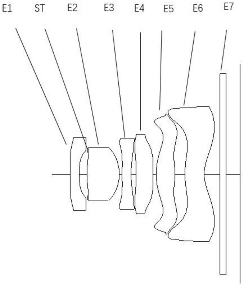
[0054] Refer to the following figure 1 , Figure 2A to Figure 2D An optical lens according to Embodiment 1 of the present invention will be described. figure 1 A schematic structural view of the optical lens according to Embodiment 1 of the present invention is shown.
[0055] Such as figure 1 As shown, the optical lens according to the exemplary embodiment of the present invention includes in sequence from the object side to the image side along the optical axis: a first lens E1, a stop STO, a second lens E2, a third lens E3, a fourth lens E4, The fifth lens E5, the sixth lens E6, the filter E7 and the imaging surface S16.
[0056] The first lens E1 has negative refractive power, its object side S1 is concave, and the image side S2 is concave; the second lens E2 has positive refractive power, its object side S4 is convex, and the image side S5 is convex; the third lens E3 has Negative refractive power, the object side S6 is convex, and the image side S7 is concave; the fo...
Embodiment 2
[0078] Refer to the following image 3 , Figure 4A to Figure 4D An optical lens according to Embodiment 2 of the present invention will be described. In this embodiment and the following embodiments, for the sake of brevity, descriptions similar to those in Embodiment 1 will be omitted. image 3 A schematic structural diagram of an optical lens according to Embodiment 2 of the present invention is shown.
[0079] Such as image 3 As shown, the optical lens according to the exemplary embodiment of the present invention includes in sequence from the object side to the image side along the optical axis: a first lens E1, a stop STO, a second lens E2, a third lens E3, a fourth lens E4, The fifth lens E5, the sixth lens E6, the filter E7 and the imaging surface S16.
[0080] The first lens E1 has negative refractive power, its object side S1 is concave, and the image side S2 is concave; the second lens E2 has positive refractive power, its object side S4 is convex, and the imag...
Embodiment 3
[0092] Refer to the following Figure 5 to Figure 6A -6D describes an optical lens according to Embodiment 3 of the present invention. In this embodiment and the following embodiments, for the sake of brevity, descriptions similar to those in Embodiment 1 will be omitted. Figure 5 A schematic structural diagram of an optical lens according to Embodiment 3 of the present invention is shown.
[0093] Such as Figure 5 As shown, the optical lens according to the exemplary embodiment of the present invention includes in sequence from the object side to the image side along the optical axis: a first lens E1, a stop STO, a second lens E2, a third lens E3, a fourth lens E4, The fifth lens E5, the sixth lens E6, the filter E7 and the imaging surface S16.
[0094] The first lens E1 has negative refractive power, its object side S1 is concave, and the image side S2 is concave; the second lens E2 has positive refractive power, its object side S4 is convex, and the image side S5 is co...
PUM
 Abstract
Description
Claims
Application Information
 - Generate Ideas
- Intellectual Property
- Life Sciences
- Materials
- Tech Scout
- Unparalleled Data Quality
- Higher Quality Content
- 60% Fewer Hallucinations
Browse by: Latest US Patents, China's latest patents, Technical Efficacy Thesaurus, Application Domain, Technology Topic, Popular Technical Reports.
© 2025 PatSnap. All rights reserved.Legal|Privacy policy|Modern Slavery Act Transparency Statement|Sitemap|About US| Contact US: help@patsnap.com