
Full-automatic injection tube detection machine

A technology of injection tube and detection machine, which is applied in the field of injection tube detection, can solve the problems of increased resistance of injection tube movement, dead angle of visual detection, and influence of visual detection, etc., and achieves the effects of improving stability, fast detection speed, and improving delivery efficiency

Pending Publication Date: 2021-01-08
无锡传奇科技有限公司
View PDF16 Cites 2 Cited by
  • Summary
  • Abstract
  • Description
  • Claims
  • Application Information

AI Technical Summary

Problems solved by technology

[0002] The injection tube is made of rubber material, and adopts a traditional transmission mechanism with fences and bottom brackets. Since the fence and bottom brackets are stationary, but the injection tube is moving, the rubber injection tube is conveyed in this way. During the process, there will be greater friction between the injection tube, the fence and the bottom bracket, which will increase the movement resistance of the injection tube and increase the difficulty of handling; at the same time, the traditional transmission mechanism has a fence and a bottom bracket There will be dead angles in visual inspection, which will affect visual inspection

Method used


Image

  • Full-automatic injection tube detection machine
  • Full-automatic injection tube detection machine
  • Full-automatic injection tube detection machine

Examples


Embodiment Construction

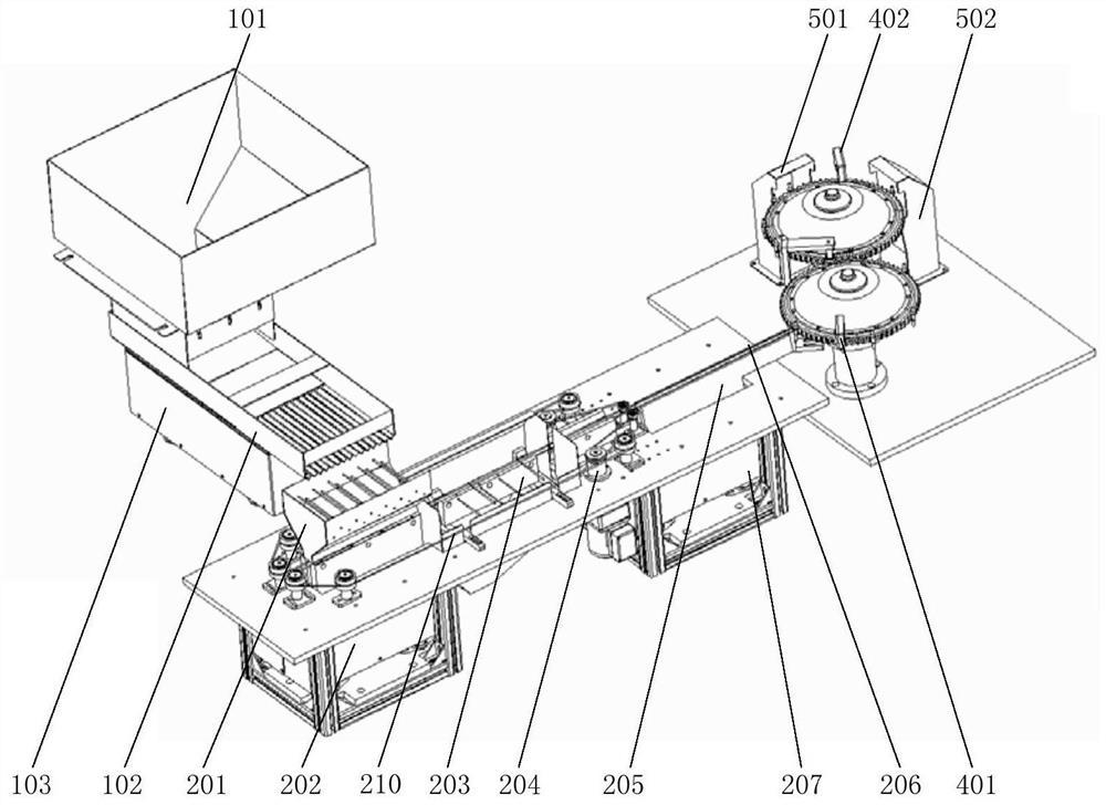
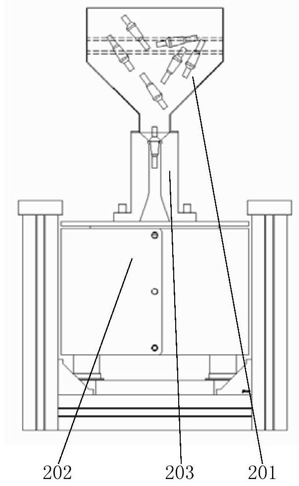
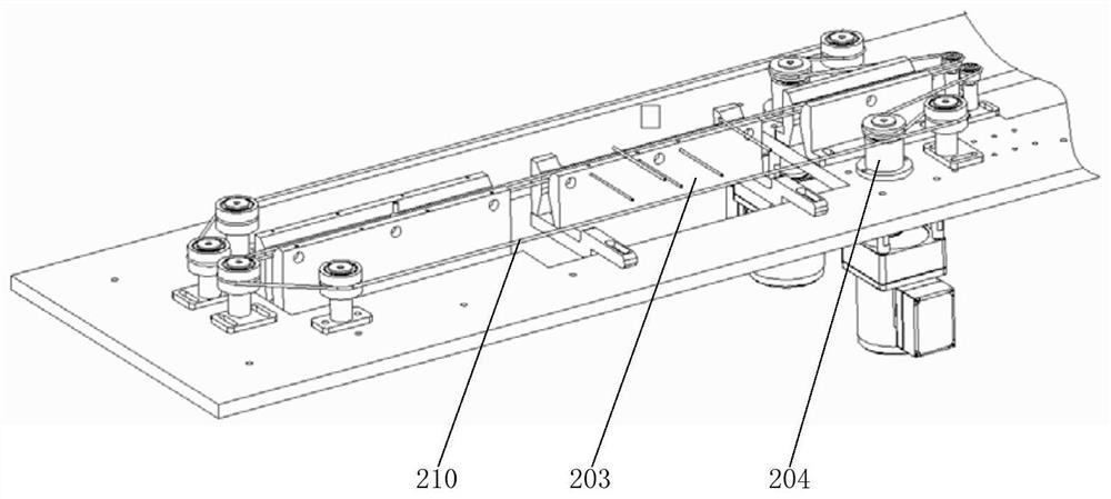
[0051] The structure specification is attached below Figure 1-7 The specific technical solutions of the present invention are further described.

[0052] as attached figure 1 As shown, the embodiment of the present invention provides a fully automatic syringe inspection machine, including: a feeding device, a conveying device, a suction turntable device, a detection device and a sorting device.

[0053] The feeding device includes a main bin 101 , a buffer bin 102 and a feeding linear vibrator 103 .

[0054] The main material box 101 is a funnel-shaped container, the bottom of which is connected to the buffer material box 102; the connection between the main material box 101 and the buffer material box 102 is provided with an adjusting plate for adjusting the discharge flow. The buffer material box 102 is a rectangular tank box, the top of one end of the buffer material box 102 is connected with the bottom of the main material box 101, the other end side is provided with a ...


PUM


Abstract

The invention provides a full-automatic injection tube detection machine. The full-automatic injection tube detection machine comprises a feeding device, a conveying device, an air suction turntable device, a detection device and a sorting device; the feeding device comprises a main material box and a feeding linear vibrator; the conveying device comprises a screening box, a screening linear vibrator, a guide rail, a circular belt and a transmission wheel set; the air suction turntable device comprises a first vacuum conveying module and a second vacuum conveying module; the circular belt is connected with the first vacuum conveying module, and the first vacuum conveying module is connected with the second vacuum conveying module; the detection device comprises a video detection module which is arranged at the edges of the first vacuum conveying module and the second vacuum conveying module; and the sorting device comprises a waste collecting module and a finished product collecting module. According to the full-automatic injection tube detection machine, the machine vision detection principle and the high-speed image processing technology are adopted, full-automatic and non-blindarea detection is conducted on an injection tube, and waste products are automatically removed; and the detection machine has the advantages of high detection speed and high detection precision.

Description

technical field [0001] The invention relates to the technical field of injection tube detection, in particular to a fully automatic injection tube detection machine. Background technique [0002] The injection tube is made of rubber material, and adopts a traditional transmission mechanism with fences and bottom brackets. Since the fence and bottom brackets are stationary, but the injection tube is moving, the rubber injection tube is conveyed in this way. During the process, there will be greater friction between the injection tube, the fence and the bottom bracket, which will increase the movement resistance of the injection tube and increase the difficulty of handling; at the same time, the traditional transmission mechanism has a fence and a bottom bracket There will be dead angles in visual inspection, which will affect visual inspection. Contents of the invention [0003] The invention provides a full-automatic injection tube inspection machine without blind spots, ...

Claims


Application Information

Patent Timeline
Patent Type & Authority Applications(China)
IPC IPC(8): G01N21/89
CPCG01N21/89
Inventor 朱红斌
Owner 无锡传奇科技有限公司
Learn More