Intelligent lock test equipment

A test equipment and smart lock technology, which is applied in the testing of mechanical parts, environment/reliability testing, machine/structural parts testing, etc., can solve problems such as failure to test the life of smart locks, and achieve a comprehensive life effect

Pending Publication Date: 2021-01-08
浙江捷博智能科技有限公司
View PDF0 Cites 3 Cited by
  • Summary
  • Abstract
  • Description
  • Claims
  • Application Information

AI Technical Summary

Problems solved by technology

In the existing smart lock testing process, the staff usually use corresponding tools to manually test the smart lock, so as to obtain test results such as life test and stability test. However, this test method only tests the smart lock under the same environmental conditions. The lock performs unlocking, opening, closing, and locking actions and records the number of operations and the problems reflected during the test. When the smart locks that pass the test are used in the corridor, they are consistent with the test results. If the smart lock is in contact with the outdoor environment When in use, it is often affected by rain, temperature, humidity and other conditions and the test results are inconsistent. It can be seen that there is a lack of a smart lock life testing device that can test the service life in various actual environments in the prior art.
[0003] Therefore, a smart lock testing device is provided in the prior art, the patent number is 2019106394832, in which the handle and password of the smart lock are realized by setting the handle test mechanism on the control box, the simulated pressing password mechanism and the simulated door opening mechanism The input life is tested, but the existing smart lock is not limited to password unlocking, so the test equipment cannot effectively and comprehensively test the life of the smart lock

Method used


Image

  • Intelligent lock test equipment
  • Intelligent lock test equipment

Examples


specific Embodiment approach

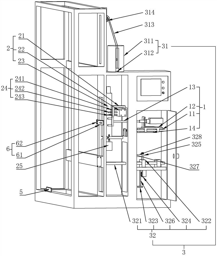
[0020]As an improved specific embodiment, the lower door opening assembly 32 includes a door opening lever 321, a door opening slide 322 and a door opening weight 323, the door opening slide 322 is fixedly installed in the control box, and one end of the door opening lever 321 Penetrate into the control box and pass through the door-opening slide 322 to be slidably arranged on the door-opening slide 322. The door-opening sprocket is rotatably connected to the position below the door-opening lever 321 in the control box. 324, the connecting piece 325 is fixed on the door opening lever 321, the door opening chain 326 is fixed on the lower side of the connecting piece 325, the upper end of the door opening chain 326 is connected on the lower side of the connecting piece 325, and the lower end bypasses the door opening sprocket After 324, it is connected with the door-opening weight 323. The control box is fixed with a reset cylinder 327 relative to the position above the door-open...


PUM


Abstract

The invention discloses intelligent lock test equipment. The equipment comprises a fixing frame, a door frame installed on the fixing frame, a door plate arranged on the door frame, an intelligent lock fixed to the door plate and a control box erected on one side of the intelligent lock; a handle test mechanism, an unlocking mechanism and a simulated door opening and closing mechanism are arrangedon the control box; the unlocking mechanism comprises an unlocking base, a transverse sliding rail, a longitudinal sliding rail and an unlocking air cylinder set; the unlocking air cylinder set comprises a password air cylinder, a card swiping air cylinder and a fingerprint air cylinder; the password air cylinder, the card swiping air cylinder and the fingerprint air cylinder are sequentially distributed on the unlocking base from top to bottom; a pressing head is fixed to the end of a pushing rod of the password air cylinder. According to the intelligent lock testing equipment, the unlockingair cylinder set is set to comprise the password air cylinder, the card swiping air cylinder and the fingerprint air cylinder; and a key air cylinder is arranged, so that beside fingerprint unlockingtest, test can be effectively performed on the other parts of an intelligent lock.

Description

technical field [0001] The present invention relates to a testing device, in particular to an intelligent lock testing device. Background technique [0002] Since smart locks are security and security facilities, they need to undergo strict monitoring and testing before leaving the factory to ensure that each batch of smart locks can be put into use stably and reliably. In the existing smart lock testing process, the staff usually use corresponding tools to manually test the smart lock, so as to obtain test results such as life test and stability test. However, this test method only tests the smart lock under the same environmental conditions. The lock performs unlocking, opening, closing, and locking actions and records the number of operations and the problems reflected during the test. When the smart locks that pass the test are used in the corridor, they are consistent with the test results. If the smart lock is in contact with the outdoor environment When in use, it is...

Claims


Application Information

Patent Timeline
Patent Type & Authority Applications(China)
IPC IPC(8): G01M13/00G01M99/00G01R31/00
CPCG01M13/00G01M99/005G01R31/003
Inventor 朱小林王阳斌周利勇
Owner 浙江捷博智能科技有限公司
Why Eureka
Try Eureka