Finished product detection device for motor shaft machining

A technology for finished product inspection and motor shaft, which is applied in the direction of mechanical measuring devices, measuring devices, and mechanical devices, etc., can solve the problems of end face runout detection of motor shafts, affecting the connection between the driving shaft and the driven shaft, etc., so as to improve efficiency and promote Effect of synchronicity, reduced time

Inactive Publication Date: 2021-01-08
舒城久联精密机械有限公司
View PDF6 Cites 12 Cited by
  • Summary
  • Abstract
  • Description
  • Claims
  • Application Information

AI Technical Summary

Problems solved by technology

[0004] Although the overall device can detect the runout of the axial direction of the motor shaft, it does not detect the runout of the end face of the motor shaft, and the runout of the end face directly affects the connection between the driving shaft and the driven shaft. Therefore, it is urgently needed A finished product detection device for motor shaft processing

Method used


Image

  • Finished product detection device for motor shaft machining
  • Finished product detection device for motor shaft machining
  • Finished product detection device for motor shaft machining

Examples


Embodiment 1

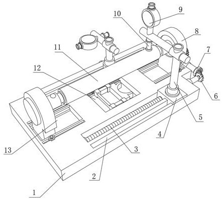
[0033] A finished product detection device for motor shaft processing, such as Figure 1-5As shown, it includes a base 1, the top outer wall of the base 1 is provided with two chute 13, and the two chute 13 are slidably connected with a fixed seat 8, and the top of the base 1 is close to the top outer walls on both sides of the two chute 13 A first fixing hole 22 is opened, and each first fixing hole 22 is slidably connected with a second fastening bolt. The middle outer wall of the top of the base 1 is provided with an installation groove 12, and the installation groove 12 is provided with a support mechanism 24. The opposite sides of the two fixing bases 8 are provided with a clamping mechanism, and the opposite sides of the two clamping mechanisms are clamped with the same motor shaft 11 , and the outer wall of the top side of the base 1 is provided with a fixing groove, and the fixing groove is formed. The inner walls on both sides are connected with the same screw 3 throu...

Embodiment 2

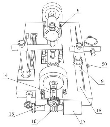
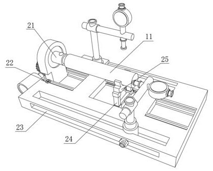
[0038] A finished product detection device for motor shaft processing, such as Figure 4-5 As shown, in order to solve the problem of installation and support of the motor shaft 11; this embodiment makes the following improvements on the basis of Embodiment 1: the support mechanism 24 includes a semicircular support plate 25, a frosted plate 26, and two limit rolling grooves 27 , two rollers 28 and two telescopic rods 29, and the two limit rolling grooves 27 are respectively opened on the inner walls of both sides of the installation groove 12, and the two rollers 28 are slidably connected to the two limit rolling grooves 27. The two ends of the plate 26 are respectively fixed on the opposite sides of the two rollers 28 by connecting blocks, the two telescopic rods 29 are respectively welded to the top outer wall of the frosted plate 26, and the semicircular support plate 25 is welded to the extension rod ends of the two telescopic rods 29. The inner ring of the semicircular s...


PUM


Abstract

The invention discloses a finished product detection device for motor shaft machining, and relates to the technical field of motor shaft detection. The end face run-out detection problem of a motor shaft is solved. The device specifically comprises a base, two sliding grooves are formed in the outer wall of the top of the base, fixing bases are slidably connected into the two sliding grooves correspondingly, first fixing holes are formed in the positions, close to the two sides of the two sliding grooves, of the outer wall of the top of the base correspondingly, second fastening bolts are slidably connected into the first fixing holes correspondingly, and a mounting groove is formed in the outer wall of the middle of the top of the base; and a supporting mechanism is arranged in the mounting groove, clamping mechanisms are arranged on the opposite sides of the two fixing bases correspondingly, the same motor shaft is clamped to the opposite sides of the two clamping mechanisms correspondingly, a fixing groove is formed in the outer wall of one side of the top of the base, and the inner walls of the two sides of the fixing groove are connected with the same screw rod through bearings. The mounting connection effect between the motor shaft and the driven shaft is effectively improved, and the perpendicularity of the end face of the motor shaft is guaranteed.

Description

technical field [0001] The invention relates to the technical field of motor shaft detection, in particular to a finished product detection device for motor shaft processing. Background technique [0002] The unbalance of the motor shaft is the main factor that causes the rotor to vibrate too much and generate noise, and it will also have a great impact on the working efficiency and service life of the motor. Therefore, the existing motor shaft needs to be axially run out during the machining process. At the same time, it will also detect the runout of its end face. [0003] After retrieval, the Chinese patent application number CN201810874704.X discloses a new energy motor shaft runout detection device, including a workbench, an active device, a control device, a driven device, and a runout detection device. The active device includes the first A casing, an active motor, an active chuck, the driven device includes a second casing, a driven motor, a gear, a rack, a driven s...

Claims


Application Information

Patent Timeline
IPC IPC(8): G01B5/00
CPCG01B5/00G01B5/0002G01B5/0004
Inventor 宋浩
Owner 舒城久联精密机械有限公司
Why Eureka
Try Eureka