
Floor drain device based on siphon position adjustment and change

A siphon and floor drain technology, which is applied in water supply devices, grease/oily substance/float removal devices, chemical instruments and methods, etc., can solve the problems of odor generation, reduced practicability of floor drain devices, and long interval.

Active Publication Date: 2021-01-08
辽宁硕航远行科技有限公司
View PDF7 Cites 3 Cited by
  • Summary
  • Abstract
  • Description
  • Claims
  • Application Information

AI Technical Summary

Problems solved by technology

[0004] According to the search, the existing authorized notification number is CN 109518791 B Chinese patent, which realizes long-term efficient water sealing and deodorization treatment for the pipeline at the bottom of the floor drain by setting a floating ball and a sealing cover, but does not take into account the need for water sealing treatment The amount of water, the water treated by the water seal will breed a large number of bacteria. In the case of high room temperature in summer, the water seal will cause a large number of bacteria to grow inside the floor drain device, resulting in peculiar smell. In winter, the room temperature is low, and the interval between showers is longer Long, the moisture in the inner wall of the siphon assembly may be lost due to the evaporation of water, resulting in the failure of the overall floor drain device to perform water sealing and deodorization, which reduces the practicability of the floor drain device

Method used


Image

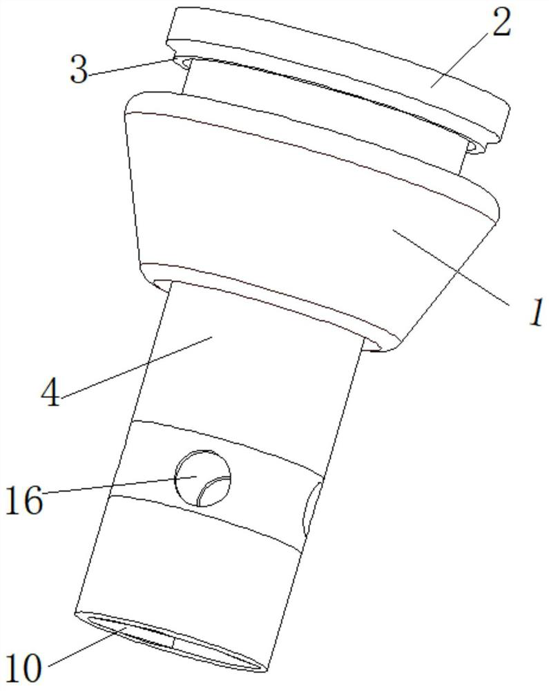
  • Floor drain device based on siphon position adjustment and change
  • Floor drain device based on siphon position adjustment and change
  • Floor drain device based on siphon position adjustment and change

Examples


Embodiment 1

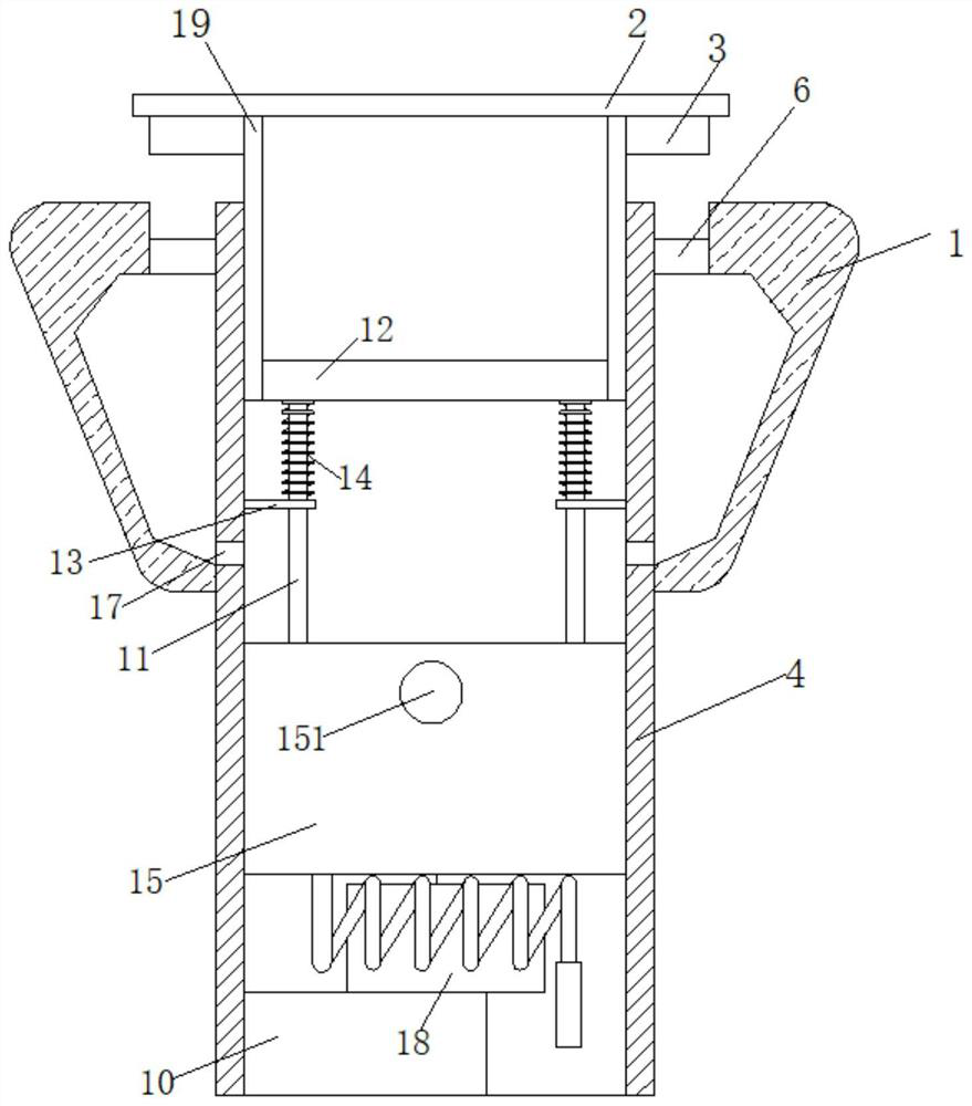
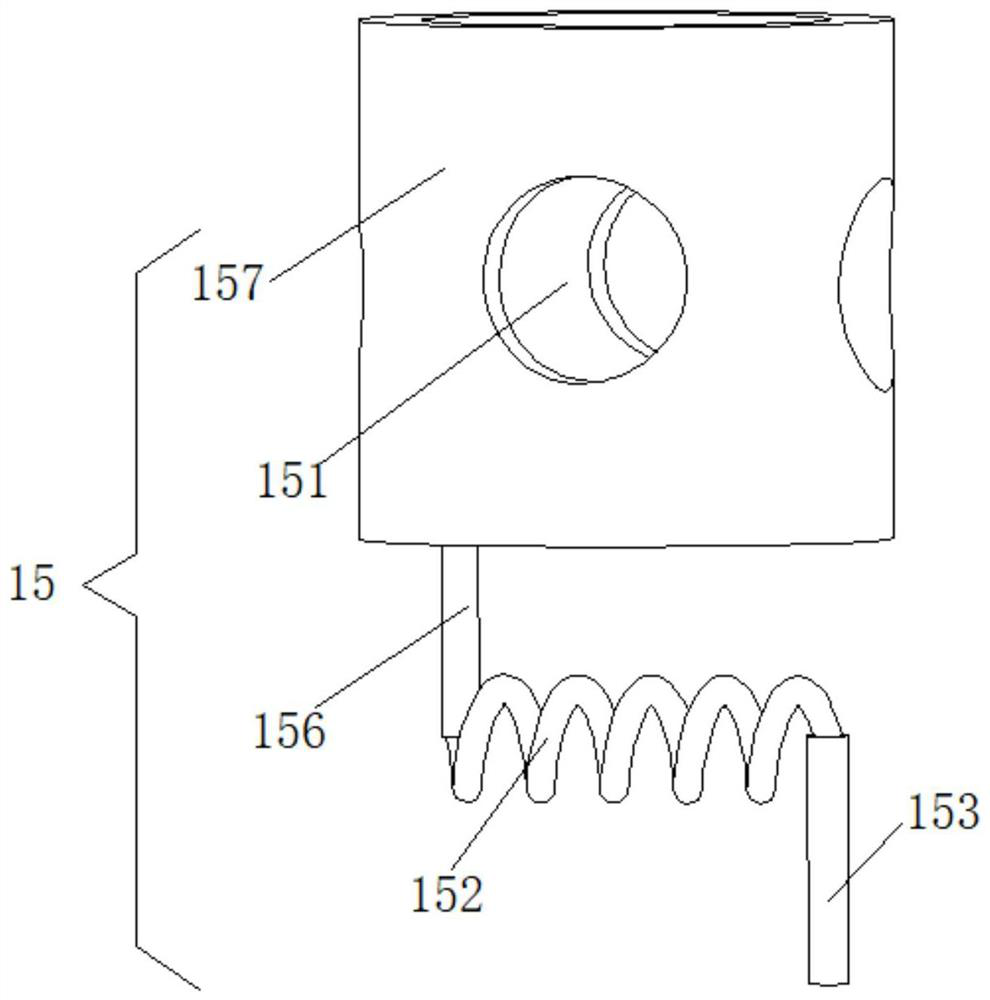
[0047] according to image 3 and Figure 4 , when there is no external water flow in, the water flow in the siphon assembly 15 will be discharged outwards through the siphon outlet hole 151 and the outlet hole 16, and when the water volume in the siphon assembly 15 is lower than the top of the siphon tube 156, the siphon assembly 15 and the siphon tube The pulling force of the common weight of the water in the assembly 15 is equal to the elastic force of the return spring 14, and the direction is opposite. At this time, the siphon pipe 156 continues to siphon and drain the threaded pipe 152 under the action of the siphon until the hose horizontal interface 154 and When the level of the temporarily stored water inside the inner wall of the siphon tube assembly 157 is equal, the siphon tube 156 stops the siphon effect, and the whole device is in a static state at this time.

Embodiment 2

[0049] according to image 3 and Figure 5 , in different seasons, the outside temperature changes differently. Under the principle of thermal expansion and cold contraction, there are three-fifths of the air and two-fifths of the sealed water in the sealed chamber 10. When the external temperature When it is lowered, the volume of the air inside the sealed chamber 10 decreases, the pressure inside the sealed chamber 10 decreases, the water seal piston 8 drives the sealing rod 9 to move downward, and under the transmission action of the hydraulic transmission device 15, the transmission rod 7 moves upward, so that The hose horizontal interface 154 moves upwards. On the contrary, as the temperature rises, the volume of the air inside the sealed chamber 10 increases, and the pressure inside the sealed chamber 10 increases. The water-sealed piston 8 drives the sealing rod 9 to move upwards. Down, the transmission rod 7 moves downward, so that the horizontal hose interface 154 mo...

Embodiment 3

[0051] according to figure 2 , image 3 , Figure 4 , Figure 5 and Figure 6 , adjusting the position of the hose horizontal interface 154 in the vertical direction is used to adjust the amount of water temporarily stored between the hose horizontal interface 154 and the bottom of the inner wall 157 of the siphon assembly. The horizontal position of the interface 154 siphons the moisture inside the inner wall 157 of the siphon assembly.


PUM


Abstract

The invention discloses a floor drain device based on siphon position adjustment and change, and relates to the technical field of floor drain devices. The floor drain device comprises a circular truncated cone part and a fixed pipe, wherein one end of the fixed pipe penetrates through the circular truncated cone part and is fixedly welded to the inner wall of the bottom of the circular truncatedcone part, the inner wall of the top of the fixed pipe is sleeved with a movable circular pipe, and a circular filter screen assembly is integrally formed at the bottom of the movable circular pipe; atransmission rod can be driven to move up and down through thermal expansion and cold contraction of air in a sealing bin, in the environment with high temperature, a hydraulic transmission device drives the transmission rod to move downwards, the water storage amount in the inner wall of a siphon assembly can be reduced, and the problem of bacterium breeding is avoided; and in the environment with low temperature, the water storage amount in the inner wall of the siphon assembly can be increased, the problem that the interval period of showering in winter is long, and consequently water in the inner wall of the siphon assembly is evaporated is solved, long-acting floor drain water sealing deodorization can be conducted, and the practicability is higher.

Description

technical field [0001] The invention relates to the technical field of floor drain devices, in particular to a floor drain device based on the adjustment and change of the position of a siphon. Background technique [0002] The floor drain is an important interface connecting the drainage pipe system and the indoor floor. As an important part of the drainage system in the residence, its performance directly affects the quality of the indoor air, and is very important for the odor control in the bathroom. [0003] At present, according to the principle of deodorization, deodorant floor drains can be divided into water seal deodorization, deodorization with cover and deodorization with floating ball. Water sealing and deodorization are the most traditional and most sensible. In the structure of the floor drain, the water storage bay is the key point. The floor drain mainly relies on the water tightness to prevent odors. However, it needs to design a water storage bay, which in...

Claims


Application Information

Patent Timeline
Patent Type & Authority Applications(China)
IPC IPC(8): E03F5/04E03F5/14
CPCE03F5/0408E03F5/041E03F5/14E03F2005/0416
Inventor 冷军
Owner 辽宁硕航远行科技有限公司
Learn More